KB Electronics KBVF-48 User Manual
Page 21
9.9
RUN/FAULT RELAY
– The Run/Fault
Relay is built-in on
Models KBVF-45, 48
and optional on
Models KBVF-27,
29. The Run/Fault
Relay Output
Contacts are located
at TB2 of the SIVFR
and can be used to turn on or off equipment or to signal
a warning if the drive is put into the Stop Mode or a
fault has occurred. See Figure 26.
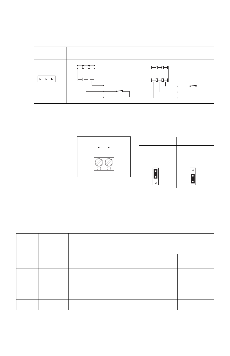
For normally open contacts, set Jumper J2 (on the SIVFR) to the “NO” position. For normally closed
contacts, set Jumper J2 (on the SIVFR) to the “NC” position. See Figure 27.
For Forward Enable Operation, wire the switch to the white and black wires. For Reverse Enable
Operation, wire the switch to the red and black wires. When the switch is closed, the drive will run.
When the switch is opened, the drive will stop.
21
FIGURE 27 – RUN/FAULT RELAY
OUTPUT CONTACT SELECTION
Normally Open Contacts
Normally Closed Contacts
Jumper J2 Installed in
“NO” Position
(Factory Setting)
Jumper J2 Installed in
“NC” Position
J2
NC
NO
J2
NC
NO
K1
K2
TB
2
Run/Fault Relay Output Contacts
FIGURE 26
RUN/FAULT RELAY CONNECTION
FIGURE 25 – ENABLE SWITCH CONNECTION
Jumper Removed
Connector Installed for
Forward Enable Switch
Connector Installed for
Reverse Enable Switch
CON2
F - S - R
(Close to Run)
Red *
(Open to Stop)
Black
White
Enable Switch
CON2
Forward
(Close to Run)
Red
(Open to Stop)
Black
White*
Enable Switch
CON2
Reverse
*For Forward Enable Switch connection, the red wire is not used. For Reverse Enable Switch connection, the white
wire is not used. The unused wire must be insulated or it may be cut off at the connector.
TABLE 4 – DRIVE OPERATING CONDITION AND RUN/FAULT RELAY CONTACT STATUS
Drive
Operating
Condition
Description
Relay Contact Status (Terminals K1 and K2 of TB2)
Run Relay Operation
(Jumper J4 Installed in “RUN” Position)
(Factory Setting)
Fault Relay Operation
(Jumper J4 Installed in “FAULT” Position)
Jumper J2 Installed in
“NO” Position
(Factory Setting)
Jumper J2 Installed in
“NC” Position
Jumper J2 Installed in
“NO” Position
(Factory Setting)
Jumper J2 Installed in
“NC” Position
Power Off
Main Power
Disconnected
Open
Closed
Open
Closed
Run Mode*
Normal
Drive Operation
Closed
Open
Closed
Open
Stop Mode*
Selected by
Operator
Open
Closed
Closed
Open
Fault**
Drive Tripped
Open
Closed
Open
Closed
* Run Mode or Stop Mode is selected using the Forward-Stop-Reverse Switch. ** Fault: Overload, I
2
t, Short Circuit, Undervoltage, and Overvoltage.