4 wiring diagram, 64 7. specifi cations – IAI America IX-NNW3515 User Manual
Page 70
64
7. Specifi
cations
Notes
(1)
The actual la
y
out
of board conn
ec
tors varies from t
h
is draw
ing.
(2)
Since the brake
po
w
e
r circuit is pr
ovided on the p
rimary
side (high-voltage side)
, a dedicated 24 V po
w
e
r suppl
y
is req
uire
d for
this circuit. The 24 V po
w
e
r suppl
y for I/O circuits used on the secon
dary
si
de (lo
w-vo
ltage side) cannot be shared.
(3)
To operate the al
arm LED, the
user must provide
a circuit that uses the controller I/
O output signal.
(4)
With the dust-pro
of/splash-proof s
pecification, the user connector is w
a
terp
roof.
(5)
FG of t
he dust-p
roof/splash-proof
specificat
ion is connected to pin 1
6 of the connecto
r.
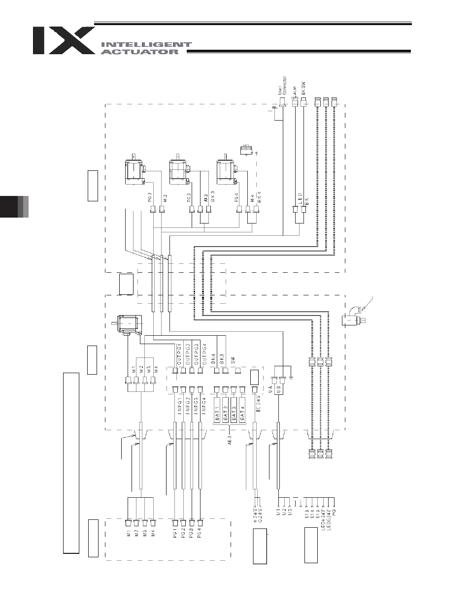
7.4 Wiring
Diagram
Wiring/Piping Diagram (Arm Length: 250/350)
Co
n
tro
lle
r
C
abl
e f
ix
cap
(C
apcon)
M cable (o
utside
robo
t)
PG ca
ble (
o
u
tside r
o
bo
t)
BK p
o
w
e
r cable (
o
u
tside r
o
b
o
t)
U cable (o
utside
rob
o
t)
Br
ake p
o
w
e
r
term
in
als
Use
r w
irin
g
term
in
als
Inside bas
e
Ser
v
o mot
or
f
or
ax
is
1 (
ar
m
1)
Boar
d
FG (
T
o
bas
e)
A
ir joint, red (
I
4)
A
ir joint, bl
ack (
I
4)
A
ir joint, w
h
ite (
I
4)
F
lex
ibl
e
cable
Insi
de ar
m 2
PG ca
ble (
inside
r
o
bo
t)
M cable (insid
e rob
o
t)
U cable (insid
e rob
o
t)
Ser
v
o mot
or
f
or
ax
is 2 (arm
2)
Ser
v
o mot
or
w
ith br
ake
for ax
is 3 (Z-ax
is)
Ser
v
o mot
or
f
or
ax
is 4 (R-axis)
FG (to D-sub
ho
using
)
D
-s
u
b
co
nne
ct
o
r
fo
r us
er wi
ri
n
g
(1
5
-p
in,
so
cke
t)
A
la
rm
LE
D
Brake-releas
e sw
itch for ax
es 3/4
(Z/R-ax
es)
A
ir joint, bl
ack (
I
4)
A
ir joint, red (
I
4)
A
ir joint, w
h
ite (
I
4)
Electromag
netic
br
ake
for
ax
is
4
(R-axis)
Dedicate
d b
a
tt
eries
fo
r IX
:
Pur
g
e ai
r i
nl
et
(t
ube di
a
m
et
er
I
6)