Caution – IAI America IX-NNW3515 User Manual
Page 38
32
6. Inspection/Maintenance
6.2.2
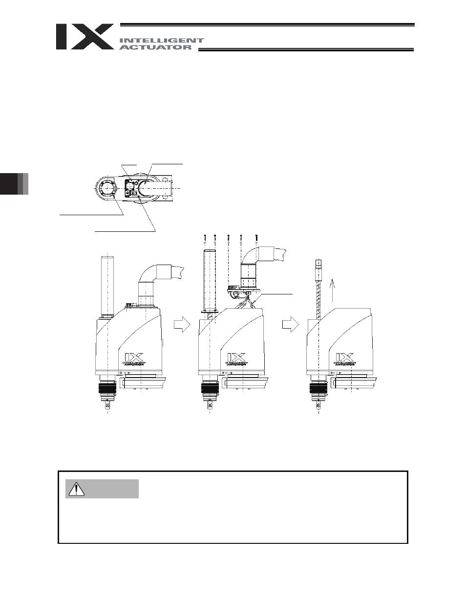
Removing the Cover
(1) With arms 1 and 2 extended as illustrated below, remove the four cap screws (M3 x 18) [1] and six
cap screw (M3 x 18) [2].
(2) Lift the panel and remove the motor connectors (M, PG, BK) from the back of the panel. (Do not
cause the wires to be pulled with excessive force when lifting the panel.)
(3) Lift the cover and remove upward.
z If the cover is removed, absolute reset must be performed again for the rotational axis and vertical
axis. (See 6.4, “Absolute Reset Procedure.”)
z Do not cause the wires to be pulled with excessive force when lifting the panel.
Rotary joint
[1] CAP 4 - M3 x 18
(with sealing washer)
Panel
Remove the motor
connectors.
Lift the cover and
remove upward.
Caution
[2] CAP 6 - M3 x 18
(with sealing washer)