Warning – IAI America IX-NNW3515 User Manual
Page 56
50
6. Inspection/Maintenance
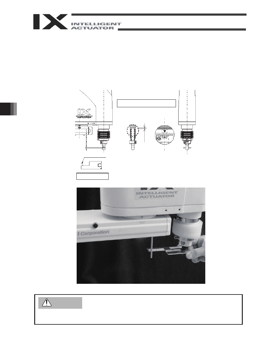
(8) Affix the rotational axis at the reference position by setting the plate and pin of the adjustment jig as
illustrated below.
Set the jig after confirming that the emergency-stop switch is pressed.
1) Confirm that the rotational axis is roughly in the reference position. (Vertical positioning marks
should align. The D-cut surface should be on the right side when viewed from the front.)
2) Set a plate jig on the rotational axis by causing its side labeled “UPPER (ARM SIDE)” to face up.
3) Insert a pin jig from the bottom to set the rotating direction of arm 2.
4) Turn the rotational axis until the plate jig contacts the pin lightly.
z Always press the emergency-stop switch before setting an adjustment jig. Failure to do so may
cause the robot to malfunction and result in a serious accident.
Reference position drawing
Positioning
mark label for
rotational axis
Cause the jig to lightly
contact the pin.
Lift the spline until the
stopper is contacted,
and then lower by
approx. 4 mm.
A
pprox. 4 mm
Inside bellows
View from below
Warning