2 external dimensions, 61 7. specifi cations – IAI America IX-NNW3515 User Manual
Page 67
61
7. Specifi
cations
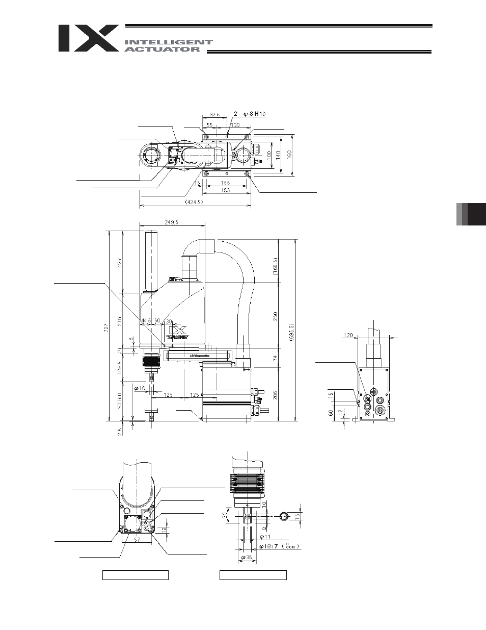
7.2 External
Dimensions
IX
NNW 2515 (Arm Length 250, Dust-proof/Splash-proof Specification)
Arm 1 stopper
4 -
I9
I16, counterbore depth 0.5
4 (M
echanical end)
Spacer for user part
installation
Height 10, M4, depth 5 (*1)
*1: External force applied to the spacers must
not exceed 30 N in the axial direction or 2
N
m in the rotating direction (for each
spacer).
*2: The LED operates only when the user
provides a circuit that receives controller I/O
output signal and supplies 24 VDC to the
LED terminal in the user connector.
Reference
surface
Reference
surface
ALM (indicator)
Arm 2 stopper
I4 quick air-tube joint
(black, red, white; 3 locations)
BK SW (Brake-release switch)
Tapped hole for
peripheral installation (4
locations, M4, depth 12)
T-slot for
peripheral
installation
(M3, M4)
I4 (red) quick joint
I4 (black) quick joint
I4 (white) quick joint
Detailed view of panel
(inner diameter)
User connector
Same on opposite
surface
Detailed view of arm tip
Purge air inlet:
Outer diameter
I6
(inner diameter
I4)
BK SW (Brake-release switch)
User connector
(15-pin connector)
ALM (red LED) (*2)