IAI America LSA User Manual
Page 13
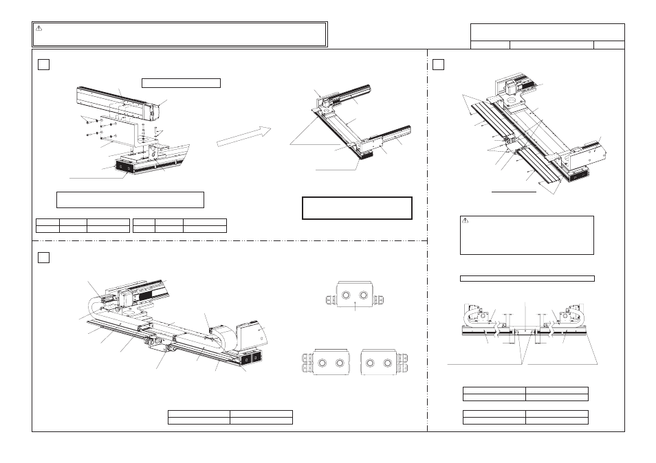
Caution: z Although each part has been chamfered to remove sharp edges, exercise due caution during
the assembly to prevent injury. If necessary, wear gloves or other protective gears.
z Exercise due caution during the assembly to prevent pinching of hands and fi ngers.
ICSPA6-B2L1HS3M
30
30
43
43
1
3
2
GMM07-072
1/4
Drawing No.
Hexagonal bolt M8s40
+ high-tension washer
(4 sets)
Parallel pin (1 pc or 2 pcs)
Hexagonal socket head bolt M8s30
+ high-tension washer (4 sets)
Parallel pin (2 pcs)
Y1-axis: ISPA
[1] XY bracket
X-axis: LSA
X-axis base, reamed-hole side
[Tools] Allen wrench, spanner wrench
Assembly of Y1-axis side
[Installation of X-axis: LSA on XY bracket [1]]
[Installation of Y1-axis: ISPA on XY bracket [1]]
Note: To ensure squareness between the X-axis and Y-axis, insert one parallel pin.
Adjust the angle between the X-axis and Y-axis to the right angle, and then
mount the hexagonal bolts.
Parallel pin Hexagonal bolt
Tightening torque
F6h7s15
M8s40mm
306kgfvcm/2997Nvcm
Parallel pin
Hexagonal socket
head bolt
Tightening torque
F8h7s18
M8s30mm
306kgfvcm/2997Nvcm
Hexagonal socket head bolt M4s10 (2 pcs)
Hexagonal socket head bolt M4s10 (2 pcs)
Hexagonal socket head bolt M4s10
+ hexagonal nut (2 sets)
Hexagonal socket head bolt M4s10
+ hexagonal nut (2 sets)
Y2-axis: ISPA
X-axis: LSA
Y1-axis: ISPA
Track mounting bracket
[3] Guide rail
[4] Cable track 1
[4] Cable track 1
[3] Guide rail
Track mounting bracket
Tightening torque
Hexagonal socket head bolt
[Installation of cable track 1 [4] on track mounting bracket]
[Installation of guide rail for cable track 1 [4] in T-slot]
M4s10mm
36.7kgfvcm/359Nvcm
In this assembly procedure, the controller-actuator cable is
taken out from the wiring box in the direction shown above.
The cable can also be taken out in the directions shown below.
Wiring box
Y1-axis: ISPA
X-axis: LSA
Y2-axis: ISPA
[1] XY bracket
X1-axis slider side
(base, reamed-hole side)
X2-axis slider side
(base, slotted-hole side)
[2] XY bracket
(different direction)
* The direction is different on the Y2-axis side.
Assemble the parts by referring to
the Y1-axis side.
[4] Cable track 1
[3] Guide rail
[4] Cable track 1
[6] Wiring box bracket
[3] Guide rail
Affixing positions of guide rail [3], cable track 1 [4] and wiring box bracket [6]
Caution: The cables for Y1-axis side (axes 1, 2 and 3) and Y2-axis side
(axes 4, 5 and 6) are placed in tracks. Install each cable correctly.
[Cable markings]
v Y1-axis side (axes 1, 2 and 3):
v Y2-axis side (axes 4, 5 and 6):
1-M, PG, (LS), 2-M, PG, (LS),
3-M, PG, (LS)
4-M, PG, (LS), 5-M, PG, (LS),
6-M, PG, (LS)
Flange socket
(hexagonal socket head type)
M4s10
+ hexagonal nut (3 sets)
Hexagonal socket head bolt M4s6
+ hexagonal nut (2 sets)
Flange socket (hexagonal socket head type) M4s10
+ hexagonal nut (3 sets)
Y1-axis: ISPA
Y2-axis: ISPA
X-axis: LSA
[8] Grommet with film
[3] Guide rail
[6] Wiring box bracket
[3] Guide rail
[9] Controller-actuator cable with
cable fix cap (for axis 4, 5 or 6)
[9] Controller-actuator cable with
cable fix cap (for axis 1, 2 or 3)
X-axis Linear Servo Type Cartesian Robot – High-precision 6-axis Specification,
Z Slider Mount
Track mounting bracket
(Already attached to LSA)
Track mounting bracket
(Already attached before delivery)
Attach to the upper T-slot.
Align the guide rail [3] surface with the end
face of the base. (Same on the other side)
Affix the wiring box bracket [6] using the holes
on the inner side, and use the upper T-slot.
[Installation of guide rail [3] in the upper T slot on X-axis: LSA side]
[Installation of wiring box bracket [6] in the upper T slot on X-axis: LSA side]
Hexagonal socket head bolt
M4s6mm
18.0kgfvcm/176Nvcm
Hexagonal socket head bolt
Flange socket (hexagonal socket head type)
Hexagonal socket head bolt
M4s10mm
18.0kgfvcm/176Nvcm