IAI America LSA User Manual
Range of operation), First edition
Manual No.: ME0197-1A
ICSPA2-B1L
H
Configuration
direction: 1
(Range of operation)
Constituent axis
X-axis
Y-axis
Model
LSA-W21SS-I-400- (stroke) -T2-L-
ISPA-MYM-I-200-20- (stroke) -T2-AQ
ICSPA3-B1L
HB3H (M)
LSA-W21SS-I-400- (stroke) -T2-L-
ISPA-MYM-I-200-20- (stroke) -T2-AQ
ISPA-MXM-I-200-20<10>- (stroke) -T2-AQ-B
Configuration direction: 1
(Range of operation)
LSA-W21SM-I-400- (stroke) -T2-L-NT1
ISPA-MYM-I-200-20- (stroke) -T2-AQ
ISPA-MYM-I-200-20- (stroke) -T2-AQ
[1] XY
bracket
ICSPA3-B1L
HS3M
LSA-W21SS-I-400- (stroke) -T2-L-
ISPA-MYM-I-200-20- (stroke) -T2-AQ
ISPA-MZM-I-200-10- (stroke) -T2-AQ-B-NM
LSA-W21SM-I-400- (stroke) -T2-L-NT1
ISPA-MYM-I-200-20- (stroke) -T2-AQ
ISPA-MYM-I-200-20- (stroke) -T2-AQ
ISPA-MXM-I-200-20<10>- (stroke) -T2-AQ-B
ISPA-MXM-I-200-20<10>- (stroke) -T2-AQ-B
ICSPA4-B2L 1 H
Configuration direction: 1
LSA-W21SM-I-400- (stroke) -T2-L-NT1
ISPA-MYM-I-200-20- (stroke) -T2-AQ
ISPA-MYM-I-200-20- (stroke) -T2-AQ
ISPA-MZM-I-200-10- (stroke) -T2-AQ-B-NM
ISPA-MZM-I-200-10- (stroke) -T2-AQ-B-NM
Configuration
direction: 1
ICSPA6-B2L 1 HB3H (M)
ICSPA6-B2L 1 HS3M
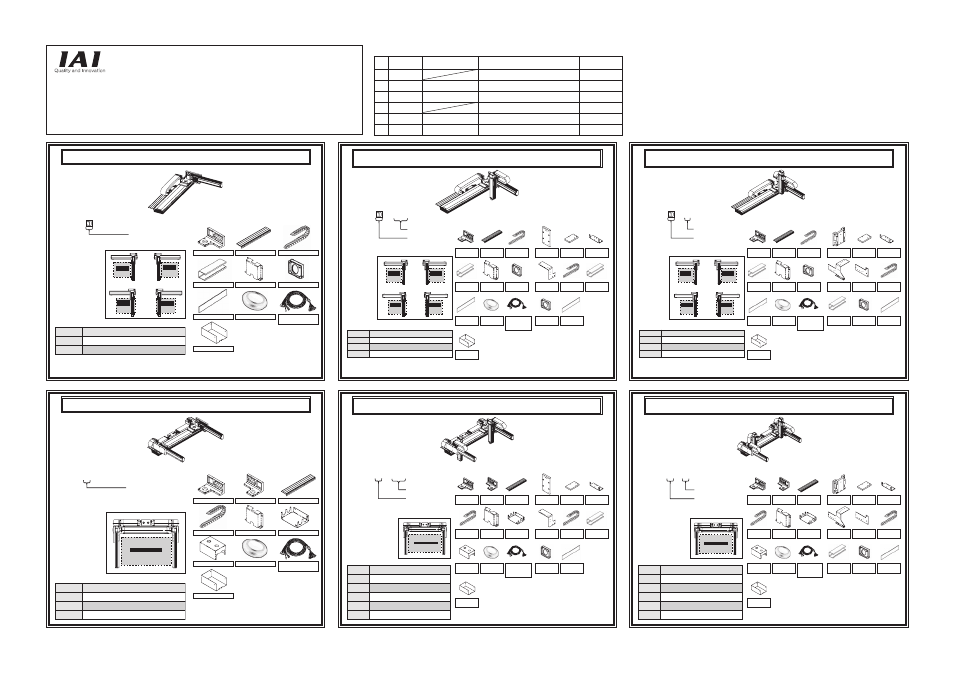
X-axis Linear Servo Type Cartesian Robot – High-precision 2-axis Specification
X-axis Linear Servo Type Cartesian Robot – High-precision 6-axis Specification,
Z-axis Base Mount
X-axis Linear Servo Type Cartesian Robot – High-precision 4-axis Specification
X-axis Linear Servo Type Cartesian Robot – High-precision 3-axis Specification,
Z-axis Base Mount
X-axis Linear Servo Type Cartesian Robot – High-precision 3-axis Specification,
Z-axis Slider Mount
X-axis Linear Servo Type Cartesian Robot – High-precision 6-axis Specification,
Z-axis Slider Mount
[Model]
[Model]
[Model]
[1] XY configuration directions
[Constituent axes]
[Assembled parts]
[Assembly Procedure] Drawing No.: GMM07-067
[1] XY configuration direction
[1] XY bracket
[2] Guide rail
[3] Cable track
[4] Connector box
[5] Connector cover
[7] Joint cover
[6] Box cover
[8] Grommet with film
[9] Controller-actuator
cable with cable fix cap
[10] Metal cover
(Range of operation)
(Range of operation)
Configuration
direction: 2
Configuration
direction: 3
Configuration
direction: 4
(Reverse of 1)
(Reverse of 3)
(Y-axis installed
on opposite side)
(Range of operation)
(Range of operation)
Configuration
direction: 2
Configuration
direction: 3
Configuration
direction: 4
(Range of operation)
(Range of operation)
(Range of operation)
(Reverse of 1)
(Reverse of 3)
(Y-axis installed
on opposite side)
Configuration
direction: 1
(Range of operation)
Configuration
direction: 2
Configuration
direction: 3
Configuration
direction: 4
(Range of operation)
(Range of operation)
(Range of operation)
(Reverse of 1)
(Reverse of 3)
(Y-axis installed
on opposite side)
Constituent axis
X-axis
Y1-axis
Model
[Model]
[1] XY configuration directions
[Constituent axes]
[Assembled parts]
[Assembly Procedure] Drawing No.: GMM07-070
[1] XY configuration direction
Y2-axis
[1] XY bracket
[3] Guide rail
[2] XY bracket
[4] Cable track
[5] Connector cover
[8] Grommet with film
[9] Controller-actuator
cable with cable fix cap
[10] Metal cover
[7] Wiring box cover
[6] Wiring box bracket
Constituent axis
X-axis
Y-axis
Model
[1] XY configuration directions
[Constituent axes]
[Assembly Procedure] Drawing No.: GMM07-068
[1] XY configuration direction
H: Z-axis high-speed type
M: Z-axis medium-speed type
[Assembled parts]
Z-axis
[Model]
Constituent axis
X-axis
Y1-axis
Model
[1] XY configuration directions
[Constituent axes]
[Assembly Procedure] Drawing No.: GMM07-071
[1] XY configuration direction
H: Z-axis high-speed type
M: Z-axis medium-speed type
[Assembled parts]
Z2-axis
Y2-axis
Z1-axis
(Range of operation)
Configuration direction: 1
(Range of operation)
Constituent axis
X-axis
Y-axis
Model
[1] XY configuration directions
[Constituent axes]
[Assembly Procedure] Drawing No.: GMM07-069
[1] XY configuration direction
M: Z-axis medium-speed type
[Assembled parts]
Z-axis
[Model]
Constituent axis
X-axis
Model
[1] XY configuration directions
[Constituent axes]
[Assembly Procedure] Drawing No.: GMM07-072
[1] XY configuration direction
M: Z-axis medium-speed type
[Assembled parts]
Y1-axis
Z2-axis
Y2-axis
Z1-axis
[2] Guide
rail
[3] Cable
track 1
[4] Connector
box 1
[5] Connector
cover
[6] Box
cover 1
[7] Joint
cover 1
[8] Grommet
with film
[9] Controller-actuator
cable
with cable
fix cap
[10] Metal
cover
[11] YZ
plate
[12] Track
mounting plate
[13] Track
support bracket
[14] Track
mounting bracket 2
[15] Cable
track 2
[16] Connector
box 2
[17] Box
cover 2
[18] Joint
cover 2
[11] YZ
plate
[12] Track
mounting plate
[13] Track
support bracket
[14] Track
mounting bracket 2
[15] Cable
track 2
[16] Connector
box
[17] Box
cover
[18] Joint
cover
[1] XY
bracket
[2] XY
bracket
[3] Guide
rail
[4] Cable
track 1
[5] Connector
cover
[6] Wiring
box bracket
[7] Wiring
box cover
[8] Grommet
with film
[9] Controller-actuator
cable
with cable
fix cap
[10] Metal
cover
[1] XY
bracket
[2] Guide
rail
[3] Cable
track 1
[4] Connector
box 1
[5] Connector
cover
[6] Box
cover 1
[7] Joint
cover 1
[8] Grommet
with film
[9] Controller-actuator
cable
with cable
fix cap
[10] Metal
cover
[11] YZ
bracket
[12] Track
mounting plate
[13] Track
support bracket
[14] Track
mounting bracket 2
[15] Track
mounting bracket 3
[17] Connector
box 2
[18] Box
cover 2
[19] Joint
cover 2
[16] Cable
track 2
[1] XY
bracket
[2] XY
bracket
[3] Guide
rail
[4] Cable
track 1
[5] Connector
cover
[6] Wiring
box bracket
[7] Wiring
box cover
[8] Grommet
with film
[9] Controller-actuator
cable
with cable
fix cap
[10] Metal
cover
[11] YZ
bracket
[12] Track
mounting plate
[13] Track
support bracket
[14] Track
mounting bracket 2
[15] Track
mounting bracket 3
[17] Connector
box
[18] Box
cover
[19] Joint
cover
[16] Cable
track 2
Either of NT1 (for configurations 1 and 3) or
NT2 (for configurations 2 and 4)
comes to in the model code above.
*
Either of NT1 (for configurations 1 and 3) or
NT2 (for configurations 2 and 4)
comes to in the model code above.
*
Either of NT1 (for configurations 1 and 3) or
NT2 (for configurations 2 and 4)
comes to in the model code above.
*
X-axis Linear Servo Type Cartesian Robot
Assembly Procedures
First Edition
Thank you for purchasing an IAI product.
Assemble your product correctly by referring to these Assembly Procedures.
LSA (Large Size Linear Servo Actuator) + ISA confi guration unit
No.
Number of
confi gured axes
Z-axis installation method
Model
Drawing No.
1
2 axes
ICSPA2-B1L
□
H
GMM07-067
2
3 axes
Z-axis base mount ICSPA3-B1L
□
HB3H (M)
GMM07-068
3
3 axes
Z-axis slider mount ICSPA3-B1L
□
HS3M
GMM07-069
4
4 axes
ICSPA4-B2L1H
GMM07-070
5
6 axes
Z-axis base mount ICSPA6-B2L1HB3H (M)
GMM07-071
6
6 axes
Z-axis slider mount ICSPA6-B2L1HS3M
GMM07-072