3 firelink-400 standard detector - interior view – Hochiki FIRElink-400CM User Manual
Page 8
Page 8 of 58
FIRElink-400 Air Sampling System – Installation Manual
© 2010 Hochiki Europe (UK) Ltd
9-5-0-346/ISS4/OCT10
2.3
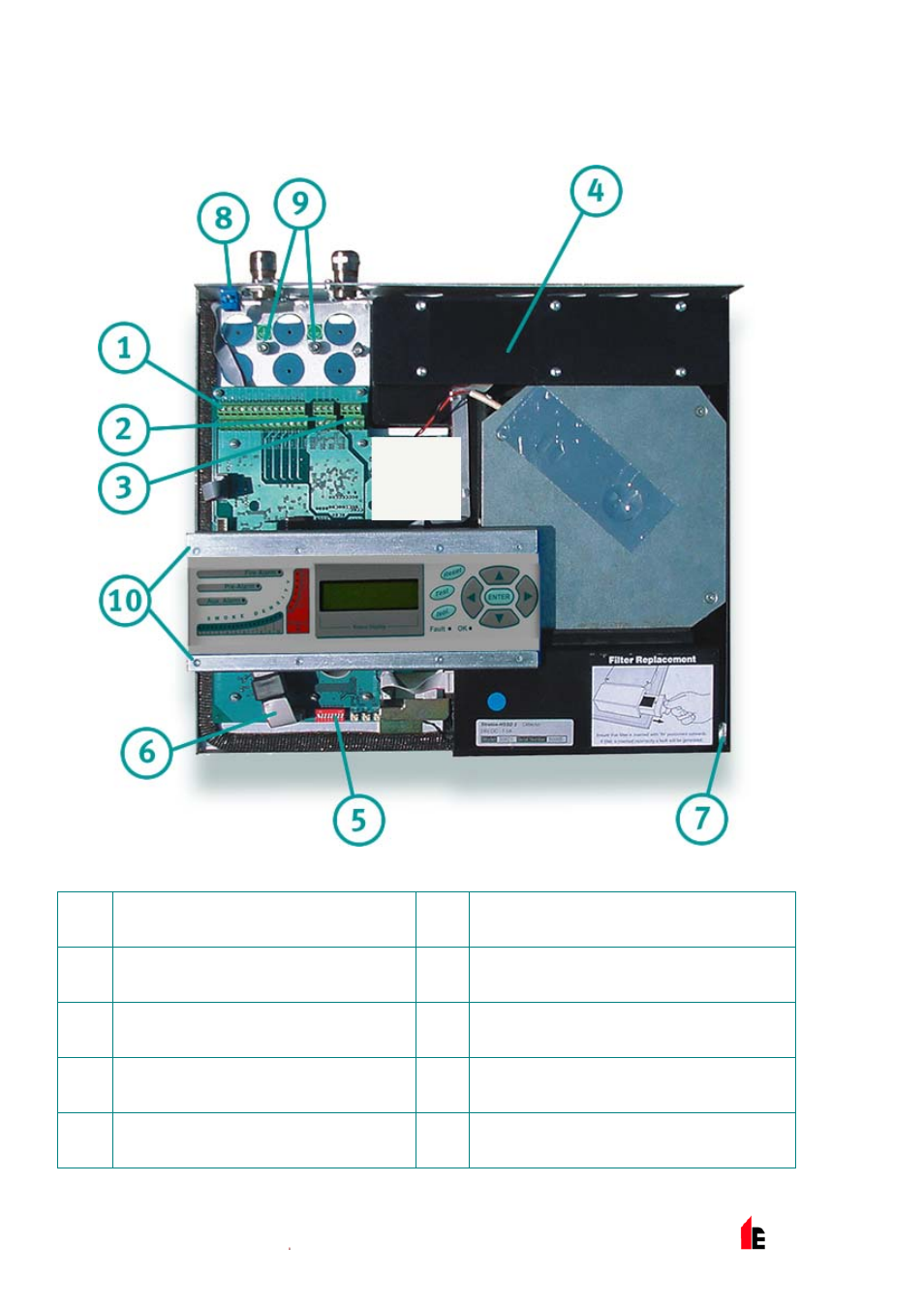
FIRElink-400 Standard Detector - Interior View
1
Terminal block connections (see section
185554080.01.1.1 on page 33)
6
Front panel display connector
2
RS485 terminal connections (see section
185554080.01.1.1 on page 33)
7
Filter removal tab (see section 11 on page
52)
3
24VDC power supply connections (see
section 185554080.01.1.1 on page 36)
8
RS232 serial port (see section 9.5 on page
49)
4
1A 5 x 20mm T-type protection fuse
9
Safety earth studs (see section 6.5 on page
36)
5
Detector address DIP switch (see section
9.1 on page 45)
10
Display fixing screws x 8 (see section
185554080.01.1.1 on page 31)
This manual is related to the following products: