Hochiki FIRElink-400CM User Manual
Page 12
Page 12 of 58
FIRElink-400 Air Sampling System – Installation Manual
© 2010 Hochiki Europe (UK) Ltd
9-5-0-346/ISS4/OCT10
Smoke density indicators
. This display is in two sections. The first part, labelled 1 to
10, is the relatively scaled ClassiFire ® bar graph and changes in steps of half a
segment. The second part displays absolutely scaled smoke levels above 1%
obscuration per metre (% obs/m) to a maximum of 25% obs/m. The Fire 2 activation
level is programmed normally somewhere in this range. The bar graph display will
show a continually cycling pattern when the unit is in FastLearn mode.
On the Command Module display, this will occur when any unit on the RS485
communications loop is in FastLearn. Otherwise, the bar graph display on the
Command Module will mimic the bar graph display on the highest-reading detector on
the loop.
Status display
(if fitted). This display shows all events as they happen in real time and
is also used to configure the unit. See section 4 “Programming the unit” on page 14 for
more information.
RESET
. When enabled, pressing
will clear any latched alarms or faults and
set the status display back to its normal operation display. To comply with national
standards, detectors are supplied with the RESET function disabled as default.
TEST
. When enabled, pressing
will start a lamp test and then the detector will
show its nominal operating sensitivity as calculated by the ClassiFire Artificial
Intelligence System.
ISOL
. Pressing
will toggle the unit‘s isolation state. When isolated, the unit
cannot generate any alarms and will signal a fault condition and the text display will
show Panel Isolate. To comply with national standards, detectors are supplied with the
ISOL button disabled as default.
NOTE: These three buttons can be individually enabled or disabled. The factory default state of the
detector is for only the
button to be enabled and for
and
to be
disabled
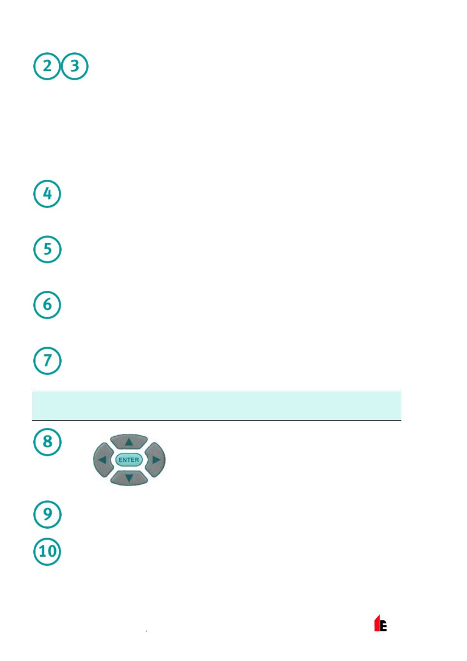
These buttons, also referred to in the text as menu buttons or by
name, for example
, are used when programming the
unit, which is pass code protected. See section 4 “Programming
the unit” on page 14 for more information. Pressing when not in
programming mode (the access code has NOT been entered)
will scroll through the detector’s event log. See section 8 “Event
Log” on page 44 for more information.
FAULT
. Illuminates when the unit has a fault and a fault signal is being sent to the fire
alarm panel. On the Command Module, this also indicates a fault in a detector on the
communications loop, or in the loop itself.
OK.
Illuminates to show normal operation when there are no faults. On the Command
Module this means that the Command Module and all detectors on the loop are
operating normally.