2 types of detectors, 1 firelink-400 standard detector – Hochiki FIRElink-400CM User Manual
Page 6
Page 6 of 58
FIRElink-400 Air Sampling System – Installation Manual
© 2010 Hochiki Europe (UK) Ltd
9-5-0-346/ISS4/OCT10
This symbol appears on the main board of the unit and indicates that the board
contains static sensitive components. Suitable anti-static precautions must be
taken when handling the board.
Hochiki Europe has taken every care to ensure that FIRElink-400 is as simple to install as possible but in
case of difficulty, please contact our Product Support Department to ensure trouble free installation and
operation (see page 2).
Hochiki Europe takes no responsibility for damage or injury occasioned as a result of failing to install or
operate the equipment in accordance with these instructions.
Throughout this manual where an entry is shown as
Example
it is meant to represent the text displayed
on the detector’s LCD screen (if fitted) when that option is selected.
Entries shown as
represent function buttons on the front of the detector.
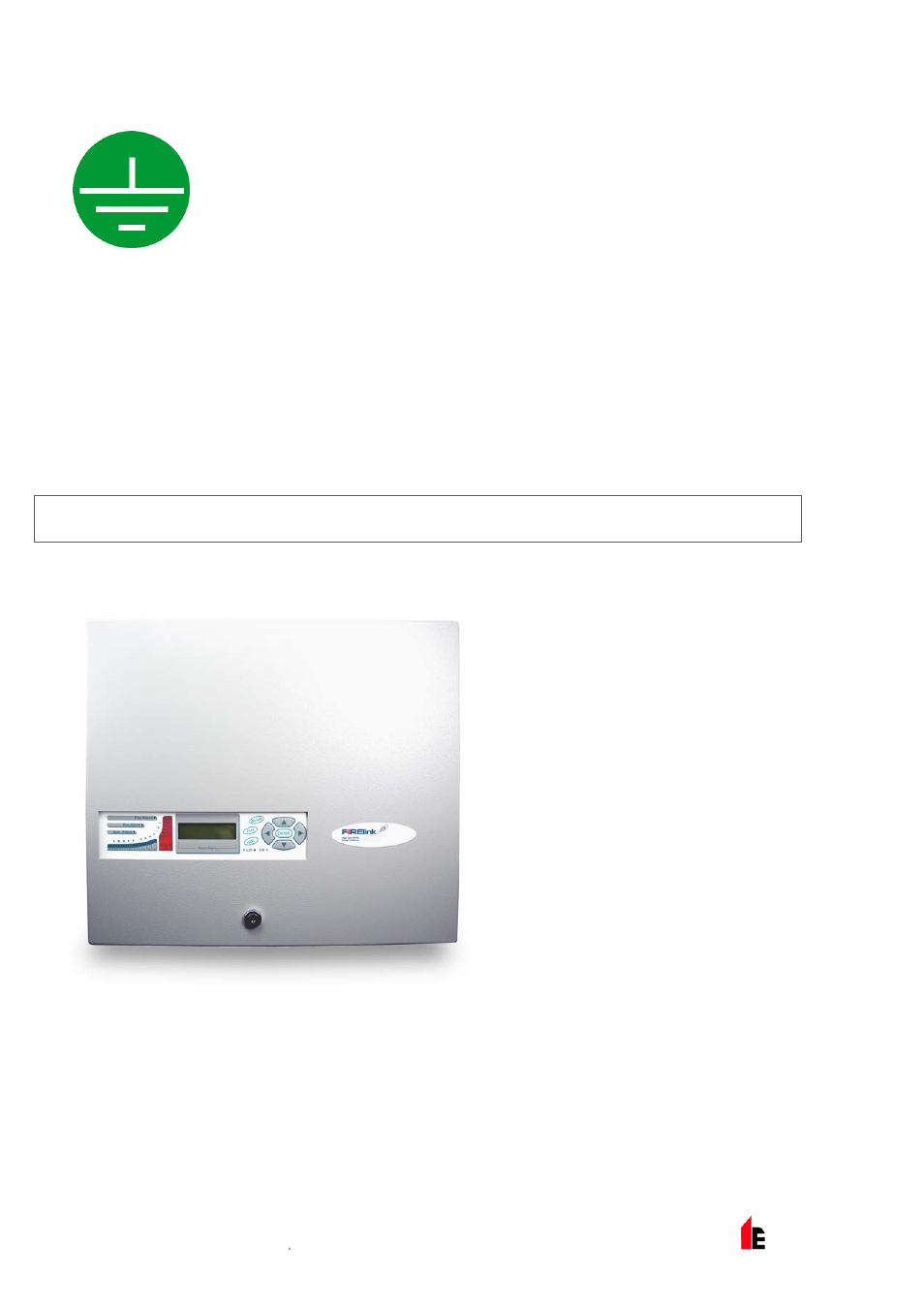
2 Types of Detectors
2.1 FIRElink-400
Standard
Detector
The Standard Detector may be operated
as a stand-alone unit, or may be part of a
network of detectors centrally monitored
by a Command Module (see "FIRElink-
400CM Command Module Detector &
FIRElink-CM Stand Alone Command
Module on page 7).
It may be programmed via the front panel
as in the version shown left. Alternatively,
and for detectors ordered without front
panel display, the detector may be
programmed remotely via the detector’s
RS485 terminals using a Command
Module, or via the detector’s RS232 port
using a PC running the remote control
software. A copy of this software is
packed with each detector supplied.