3 electrical installation – Hochiki FIRElink-400CM User Manual
Page 33
FIRElink-400 Air Sampling System – Installation Manual
Page 33 of 58
© 2010 Hochiki Europe (UK) Ltd
9-5-0-346/ISS4/OCT10
6.3 Electrical
Installation
All electrical (power and signal) connections should be made to the green terminal block inside the
detector. Power cables should be screened and of sufficient current carrying capacity. Signal cable
should be 120Ω screened twisted pair such as Belden 9841 24AWG. Power and signal cables should
enter the detector via metal cable glands.
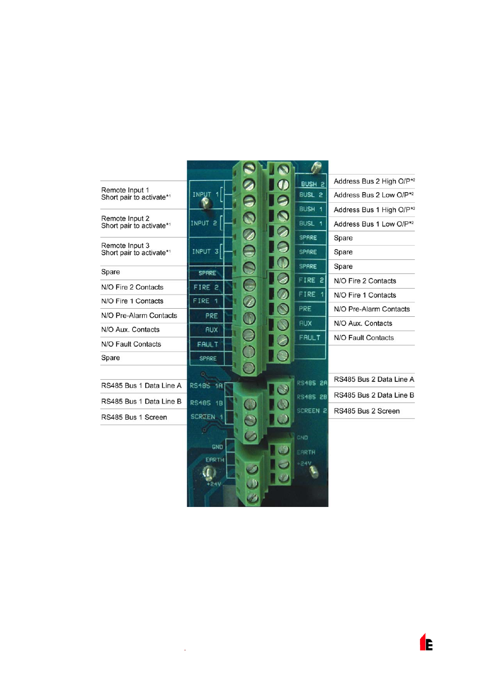
1.1.1 Detector Terminal Block Connections
Terminal block connections are as described below.
N/O = Normally Open, N/C = Normally Closed
*
1
These connections can be used as the input terminals for mains supply and battery fault sensing.
When this is the case, the contacts will signal a fault when the contacts are open rather than
closed, as fault relays operate in the opposite sense to other relays, in other words they are open
for normal operation. The factory default setting is for supply monitoring on ‘I/P 1’.
*
2
These connections are used to connect a detector to an addressable Fire Panel when the
FIRElink-APIC is fitted to the ‘Addressable Interface’ connector on the left hand edge of the detector main
PCB (see section 9.4 “Connecting a Single FIRElink-400 to an Addressable Fire Panel” on page 49).