Setup menu > air flow, Setup menu > miscellaneous – Hochiki FIRElink-400CM User Manual
Page 22
Page 22 of 58
FIRElink-400 Air Sampling System – Installation Manual
© 2010 Hochiki Europe (UK) Ltd
9-5-0-346/ISS4/OCT10
Setting this function to
Yes
puts the detector into automatic flow limit setup mode. This takes a few
minutes to set the flow fault thresholds based on the current flow rates.
1.1.1 Airflow Monitoring (Display / Numeric - Address 001-127)
Setup Menu > Air Flow
There are separate
Sensor pipe
,
Flow low
,
Flow high
and
Flow pipe
parameters for each
pipe 1 to 4 on the detector. For example,
Flow pipe 1
indicates the current airflow rate for pipe 1.
Sensor pipe 1
to
Sensor pipe 4
are used to enable or disable flow sensing on the specified
pipe inlet of the detector. If any pipe inlets are unused, set the relevant flow sensor function for the pipe
inlet to
No
to avoid unwanted flow faults.
Flow low
is the level below which airflow needs to be reduced to trigger a fault reading (which may
indicate a blocked pipe) and
Flow high
is the level above which airflow needs to increase to trigger a
fault indication (which may indicate a loose or damaged inlet pipe).
Flow low
and
Flow high
parameters are automatically set up on initial power-up or when
Flow
setup
is selected (see section 231156696.01.1.1 “Flow Setup (Yes/No - Address 001-127)” on page
21).
The airflow rates
Flow pipe 1
to
Flow pipe 4
are for display purposes only and cannot be
changed.
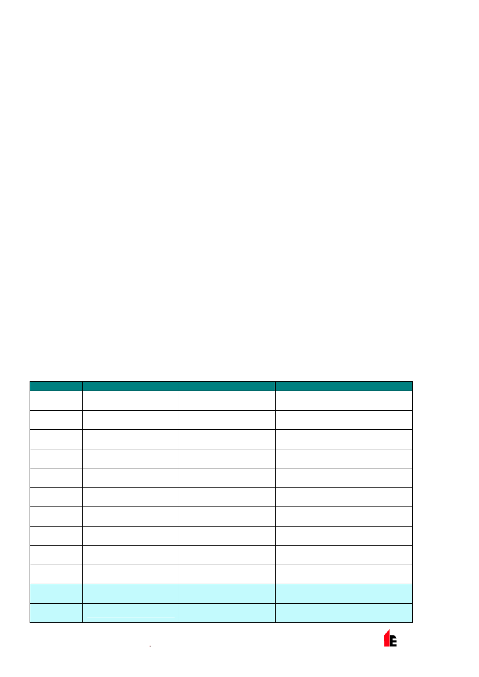
1.1.1 Chart Log Recording Rate (Numeric - Address 000-127)
Setup Menu > Miscellaneous
This function controls how frequently the detector and alarm level or flow rates are stored in the Standard
Detector or Command Module internal chart recorder log.
The chart log recording rates are as follows:
Setting
Type
Storage Interval
Time per Division on Chart Log
0
Detector Output
1 second
10 seconds
1
Detector Output
5 seconds
50 seconds
2
Detector Output
12 seconds
2 minutes
3
Detector Output
30 seconds
5 minutes
4
Detector Output
1 minute
10 minutes
5
Detector Output
2 minutes
20 minutes
6
Detector Output
5 minutes
50 minutes
7
Detector Output
10 minutes
100 minutes
8
Detector Output
20 minutes
200 minutes
9
Detector Output
50 minutes
500 minutes
10
Flow Recording
1 second
10 seconds
11
Flow Recording
5 seconds
50 seconds