Pb-dmx/32, Gilderfluke & company burbank, california – Gilderfluke&Co Pb-DMX User Manual
Page 12
When used as an input, The DMX-512 terminals accept standard DMX-512 data
from any source of DMX-512 data. This DMX-512 can come from a lighting control
board, Br-SmartMedia, Br-Brain4, Sd-50, or any other source of DMX-512. The Pb-
DMX/32 will accept data with or without GilderChecksums. If receiving GidlerCheck-
sums, the Pb-DMX/32 will not update its outputs on any DMX-512 packet that contains
an error.
When used as an output, the Pb-DMX/32 can send up to sixty-four channels worth
of DMX-512 data to control dimmers, wiggle lights, smog machines, strobe lights, or any
other devices which accept DMX-512 data.
If used to send DMX-512 data to any Gilderfluke devices (other Pb-DMX/32s, SER-
DMX, etc.), the GilderChecksums can be enabled to assure that the data is received
perfectly before it is used.
When GilderChecksums are not enabled, DMX-packets will be 512 channels in
length. This will allow frame rates up to about 40 FPS. If GilderChecksums are enabled,
the the DMX-512 packets will normally be limited to 256 channels (plus two channels for
the GilderChecksums) unless the data stored on the eeprom extends past the 256th
channel. This will cause the packets to be 512 channels in length.
To connect the Pb-DMX/32 to another DMX-512 device, wire the screw terminals as
follows:
1. Connect the DMX-512 shield to the Pb-DMX/32 DMX-512 terminal labeled ʻgroundʼ.
This is the power supply ʻgroundʼ for the Pb-DMX/32. This signal is normally found
on pin #1 of a standard DMX-512 XLR-5 connector.
2. Connect the DMX-512 negative data to the DMX-512 ʻ-ʼ input. This signal is normally
found on pin #2 of a standard DMX-512 XLR-5 connector.
3. Connect the DMX-512 positive data to the DMX-512 ʻ+ʼ input. This signal is normally
found on pin #3 of a standard DMX-512 XLR-5 connector.
The Pb-DMX/32 uses a maximum of four data channels from the DMX-512. The first
channel is used for the first eight digital outputs. The next consecutive DMX-512 chan-
nel is used for the second eight outputs, and so on. The base address used for the
DMX-512 and serial RealTime data is set using the configuration menu, or by sending
an AutoDownload file to the Pb-DMX/32 with the desired base address offset.
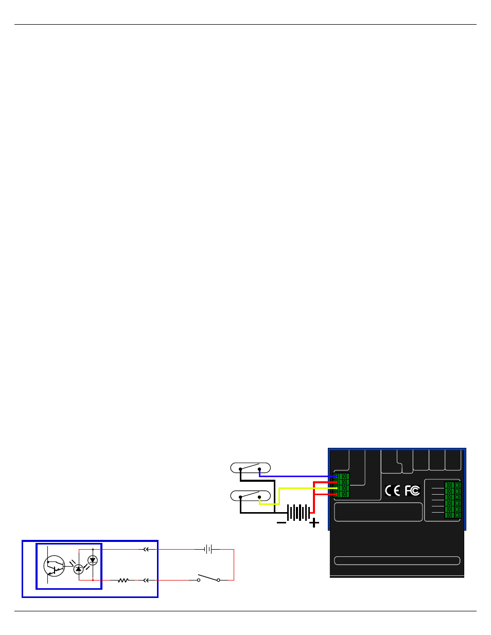
When receiving DMX-512 data, the Pb-DMX/32 no longer needs the two trigger in-
puts or their indicator LEDs. They are used as follows:
a. The ʻAʼ inputʼs Green LED is bor-
rowed to toggle on each frame
received. If receiving DMX-512
data at 30 FPS, the LED will be
flashing at 15 Hz.
b. The ʻBʼ inputʼs Green LED is bor-
rowed to flash each time there is
an er-
ror in the received
DMX-512 or Serial
RealTime data. If
you see this flash-
ing any more than
Gilderfluke & Co.• 205 South Flower Street • Burbank, California 91502 • 818/840-9484 • 800/776-5972 • fax 818/840-9485
Pb-DMX/32 v1.+ Manual / 10/31/13 / page 6 of 37
Rx -
Tx +
Gnd
Tx -
Rx +
Gnd
Input
'A'
DMX-512
Frame
Input
Rx
Data
Tx
Data
Test
DMX -512
Error
Input
'B'
DMX-512
Rx
Heart
Rs-232
note: Terminate last DMX-512
device in line with a 120! resistor
PB-DMX/32
Gilderfluke & Company
Burbank, California
This device complies with Part 15 of the FCC rules.
Operation is subject to the following two conditions: (1) This
device may not cause harmful interference and (2) this
device must accept any interference received, including
interference that may cause undesired operation.
This Class B digital apparatus meets all requirements of the Canadian Interference-
Causing Equipment Regulations.
D
M
X
-5
1
2
S
witch
Power
Supply
S
witch
Battery or Power Supply
MiniBrick8
Input 'A'
or 'B'
2.2 KΩ
Switch or Button
+
-
9 to 24 VDC
-
+
OptoIsolator