13 of 36 – Gilderfluke&Co BR-MultiBrick32 User Manual
Page 19
28
gray
channel 2 data bit 1
29
white
channel 2 data bit 0
30
black
+ VDC unregulated power supply
31
brown
circuit ground
32
red
channel 3 data bit 7
33
orange
channel 3 data bit 6
34
yellow
channel 3 data bit 5
35
green
channel 3 data bit 4
36
blue
channel 3 data bit 3
37
violet
channel 3 data bit 2
38
gray
channel 3 data bit 1
39
white
channel 3 data bit 0
40
black
+ VDC unregulated power supply
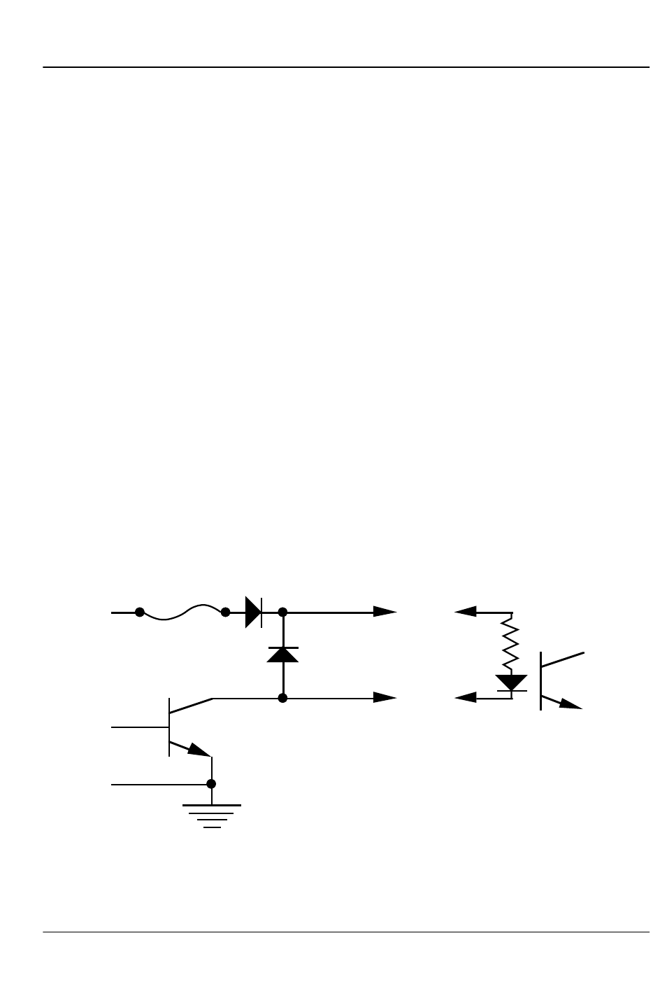
Any eight digital devices or one eight-bit analog device can
be connected to any 1/4 J-6 cable as shown. The LED between
the ground (pin #1 brown) wire and supply (pin #10 black) wire
acts as an indicator that is lit if the fuse for that channel is OK.
All outputs are open collector switches to ground. Flyback
diodes are included in the outputs for driving inductive loads.
Power is supplied through a diode and a solid state circuit breaker
to the common pin(s) on the connector. A safe level of current is
150 milliamperes simultaneously on each output. This is sufficient
to drive most small relays, valves and other similar loads directly. If
fewer than eight outputs are on at one time, then the outputs are
rated as follows.
typical output
typical input
fuse
flyback
diode
supply
supply
The supply line for each 1/4 J-6 is PTC fused for 1 amp. You
should treat each 1/4 J-6 as an individual, and not cross the out-
puts or supply lines from one channel to the lines from any other
G
ILDERFLUKE
& C
O
.• 205 S
OUTH
F
LOWER
S
TREET
• B
URBANK
, C
ALIFORNIA
91502 • 818/840-9484 • 800/776-5972 •
FAX
818/840-9485
E
AST
C
OAST
/F
LORIDA
O
FFICE
• 7041 G
RAND
N
ATIONAL
D
RIVE
• S
UITE
128d • O
RLANDO
, F
L
. 32819 • 407/354-5954 •
FAX
407/354-5955
13 of 36