11 of 36 – Gilderfluke&Co BR-MultiBrick32 User Manual
Page 17
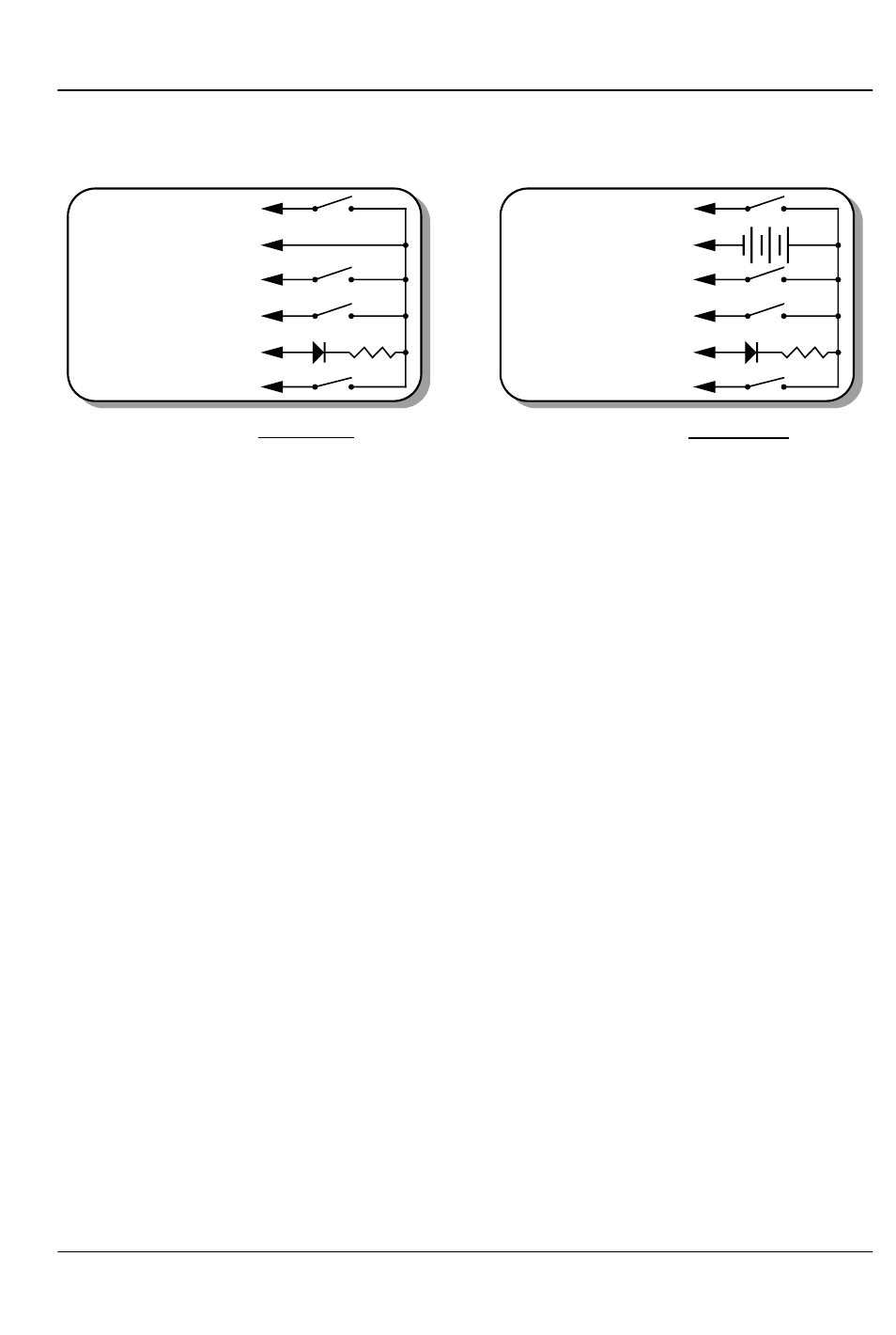
play. Facing the end of the wire, with the latch upwards, the
pinout of a standard ‘J8’ cable is as follows.
+
+ 12 to 24 VDC SUPPLY
BLUE #6 (Input C')
YELLOW #5 (status out)
GREEN #4 (Input 'A')
RED #3 (Input 'B')
BLACK #2 (common)
WHITE #1 (Input 'D')
2.2K-4.7k
LED
2.2K-4.7k
LED
J8 with Sw8 set for INTERNAL power
J8 with Sw8 set for EXTERNAL power
BLUE #6 (Input 'C')
YELLOW #5 (status out)
GREEN #4 (Input 'A')
RED #3 (Input 'B')
BLACK #2 (common)
WHITE #1 (Input 'D')
Any event can be triggered on either the ‘closing’ or ‘opening’
edge of any input. A ‘closing’ is when you apply a voltage to an
input. An ‘opening’ is when that voltage is removed. The inputs
can be triggered on any voltage from 12 to 24 VDC. If you don’t
have an external source of power for these two inputs, you can
‘steal’ some juice from the BR-MultiBrick32’s power supply connec-
tions by putting the ‘J8 Power’ switch in the ‘Internal’ position.
Power Supply: The last ten contacts of the BR-MultiBrick32’s edge
connector are used for the power supply connections. The BR-
MultiBrick32 can be run from any supply voltage from 9-24 VDC.
The outputs are powered from this supply connection as well. If
you are driving 24 VDC loads, then run the BR-MultiBrick32 on 24
VDC. If your loads require 12 VDC, then run the BR-MultiBrick32
on 12 VDC.
This input is protected from reversed polarity. An idle BR-
MultiBrick32 draws only about 200 milliamperes. The loads which
the BR-MultiBrick32 is controlling will usually draw far more current
than the BR-MultiBrick32 itself.
Digital Outputs:
Each BR-MultiBrick32 has thirty-two outputs
(hence, the name). These are just like the standard outputs used
on all Gilderfluke & Company Show Control Systems. Card cages
to hold the BR-MultiBrick32s are available with screw terminals or
ribbon cable connections.
The Output connections for all Gilderfluke & Company Show
Control Systems are through ‘J-6’ output cables. These are forty
wire ribbon cables which are made up of four identical eight-bit
wide ‘channels’. A J-6 cable is often split up into four individual
channels. Each ‘1/4 J-6’ ribbon cable is made up of ten wires,
G
ILDERFLUKE
& C
O
.• 205 S
OUTH
F
LOWER
S
TREET
• B
URBANK
, C
ALIFORNIA
91502 • 818/840-9484 • 800/776-5972 •
FAX
818/840-9485
E
AST
C
OAST
/F
LORIDA
O
FFICE
• 7041 G
RAND
N
ATIONAL
D
RIVE
• S
UITE
128d • O
RLANDO
, F
L
. 32819 • 407/354-5954 •
FAX
407/354-5955
11 of 36