System installation, 5 typical system diagram, 1 removal and installation of door – Robertshaw SlimZone CLASSIC ZONE CONTROL SYSTEM User Manual
Page 6
3.5
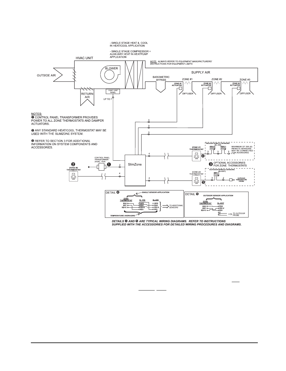
TYPICAL SYSTEM DIAGRAM
Figure 3.1: SlimZone Classic System Diagram
4.
SYSTEM INSTALLATION
4.1
REMOVAL AND INSTALLATION OF DOOR
Installer should touch a grounded metal object before handling the control panel to avoid
potential loss of operation due to static discharge. The door is hinged on the left side.
Open the door by gently pulling on the bottom right corner. Apply finger pressure only. The
door may be removed once opened by applying a slight backward pressure. Replace the door
by hooking around the tabs on the left side of the base panel and snapping back into place.
SlimZone Classic
4
Classic
Not available
with model
2701-006
See also other documents in the category Robertshaw Water boiler:
- 800 (2 pages)
- 9400 (2 pages)
- 9401 (12 pages)
- 9400 (11 pages)
- 9405 (2 pages)
- 9405 (12 pages)
- 9415 (2 pages)
- 9415 (12 pages)
- 9500 (2 pages)
- 9500 (11 pages)
- 9505 (2 pages)
- 9505 (11 pages)
- 9520 (2 pages)
- 9520 (12 pages)
- 9550 (2 pages)
- 9555 (2 pages)
- 9555 (12 pages)
- 9560 (2 pages)
- 9600 (2 pages)
- 9600 (12 pages)
- 9610 (2 pages)
- 9610 (12 pages)
- 9615 (2 pages)
- 9615 (12 pages)
- 10-531 TAP-1 Adaptor (1 page)
- 200 SERIES (2 pages)
- 300-201 (2 pages)
- 300-202 (2 pages)
- 300-203 (2 pages)
- 300-204 (2 pages)
- 300-205 (2 pages)
- 300-206 (2 pages)
- 300-207 (2 pages)
- 300-208 (2 pages)
- 300-227 (2 pages)
- 300-229 (2 pages)
- 400 SERIES (2 pages)
- 8400-1 (2 pages)
- 8405-1 (12 pages)
- 8406-1 (12 pages)
- 8425-1 (2 pages)
- 8600-1 (2 pages)
- 8601-1 (12 pages)
- 8625-1 (14 pages)
- 900 SERIES (2 pages)