Led status indication, Operation check list – Robertshaw SlimZone CLASSIC ZONE CONTROL SYSTEM User Manual
Page 13
7.
LED STATUS INDICATION
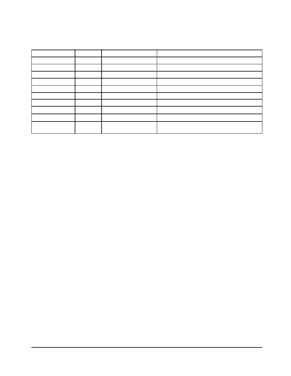
All relay outputs and system status can be verified at the control panel and are indicated
by LEDs (light emitting diodes). Refer to Figure 4.2 for location of the LEDs.
REFERENCE
COLOR
LOCATION
FUNCTION
POWER ON
Green
24VAC terminal
Panel is powered
FAULT
Red
24VAC terminal
Short in system
ZONE 1
Green
Zone 1 terminal
Damper open
ZONE 2
Green
Zone 2 terminal
Damper open
ZONE 3
Green
Zone 3 terminal
Damper open
G
Green
Equipment terminal
Fan relay energized
Y1
Yellow
Equipment terminal
Cooling/compressor relay energized
W1
Orange
Equipment terminal
Heating relay energized
B
Orange
Equipment terminal
Reversing valve relay energized in heating
NORMAL WHEN
Green
Upper right corner
Panel functioning properly
FLASHING
Table 7.1: LED Description
8.
OPERATION CHECK LIST
Verify that the following controls have been properly configured, installed and adjusted.
1.
High limit
2.
Low limit
3.
Static pressure or barometric bypass damper
4.
All thermostats low setpoint at 68°F (20°C) and high setpoint at 76°F (24°C)
5.
Tag all wiring and system components to correspond to the zone they serve
6.
If HVAC unit incorporates an economizer, it is important that it be checked for proper
operation and that the minimum positioning stop be set.
7.
If the HVAC unit has an economizer that is not equipped with a relief damper, it may be
necessary to relink the return air damper so that it will always remain thirty percent (30%)
open, otherwise the bypass damper system may not perform properly.
SlimZone Classic
11