Using cascaded computers, Testing specific links to cascaded computers, 14 testing specific links to cascaded computers – Adder Technology Switch User Manual
Page 15: Above - see, Tips for successful cascading, For more details
14
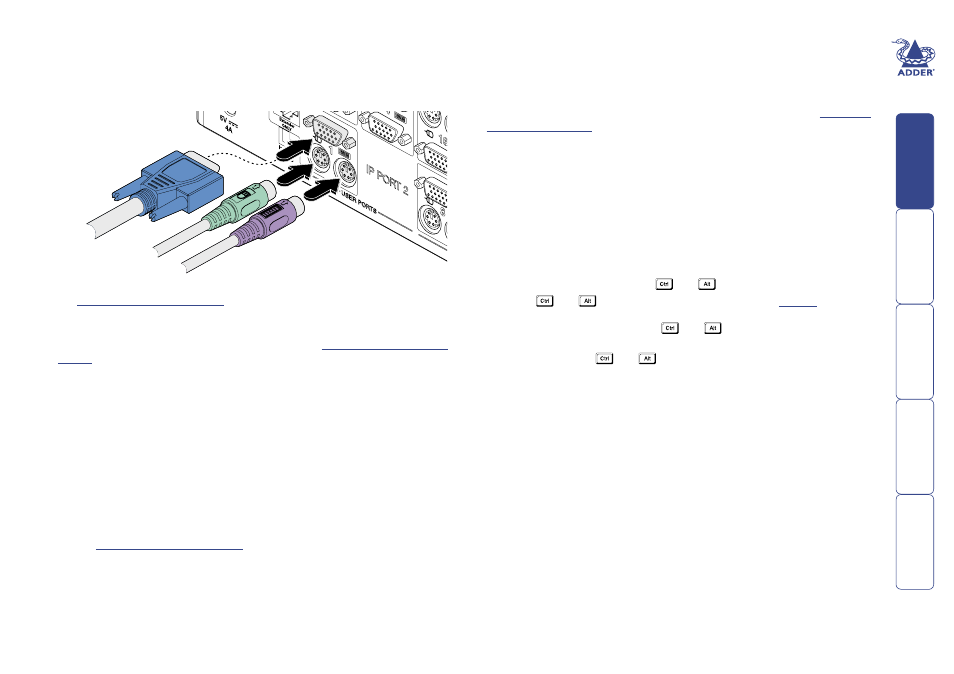
4 Connect the plugs at the other end of the KVM cable set to the keyboard,
video and mouse sockets of a User port on the rear panel of the lower
switch. Due to the way in which ports within a group are dynamically
allocated, it is not usually important exactly which user port is connected to
each computer port of the upper switch.
Using cascaded computers
In use, cascaded computers can be accessed using exactly the same methods
as for those connected directly to the SmartView World. However, by far
the easiest way is to use the on screen menu. This is because it displays the
computer names and does not require any knowledge of port addresses, some
of which (as discussed above) can be up to eight digits long. See the
section in the Operation chapter for more details.
Testing specific links to cascaded computers
As mentioned previously, the best and most efficient way to access cascaded
computers is by using the on screen menu and via non-specific routes through
the link groups. However, during configuration or troubleshooting, it may be
useful to test specific routes to computers in order to verify the various strands
of each link group. By using specific port addresses for each switch, rather than
link group numbers, you can precisely navigate a route through any part of the
system.
To test a specific link
1 Simultaneously press and hold
and
.
Note:
and
are the standard hotkeys and can be
clashes with other devices or software. If you change the hotkeys, remember
to use the new ones in place of
and
when following these
instructions.
2 While still holding
and
, in sequence, press and release the full
address of the required computer – remember to use specific port numbers,
not link group addresses, e.g. port 01140203.
3 When the last digit has been entered, release all keys.
5 Repeat steps 3 and 4 for each of the links within the group, adhering to the
for the correct link group boundaries on the
computer ports on the upper switch.
Once the switches and computers have been connected, you can edit their
names to make it much easier to locate them. See the
section in the Configuration chapter for more details.
Tips for successful cascading
• The maximum number of levels for a cascade is four.
• The number of links between switches determines the number of simultaneous
users that can access the computers situated further down the tree.
• Keep all cascade cables as short as possible to maximise video quality.
• Ensure that multiple cascade links (within a group) between switches are
approximately the same length.
• If SmartView Pro switches are used, ensure that they are situated at the
lowest level, with no SmartView World or XPro switches below them.
• Link groups of twos, threes and fours may be mixed on one switch providing
each size of group lies within the appropriate port boundaries designated in
the
. For instance, a group of each size could
be accommodated in the first nine ports of a switch providing they were
arranged as follows:
• Group of four – connected to ports 1, 2, 3 and 4 (designation 41)
• Group of two – connected to ports 5 and 6 (designation 23)
• Group of three – connected to ports 7, 8 and 9 (designation 33)
All of these connections lie within the set boundaries for each link group size.