Finish Thompson SP11/15 SERIES SELF-PRIMING User Manual
Page 6
Unpacking and Inspection
Unpack the pump and examine for any signs of shipping damage. If damage is detected, save the packaging
and notify the carrier immediately.
Section I - Assembly
Tools Required:
Metric socket or wrench set, 9/16” socket or wrench, 8 mm Allen wrench, and 3/16” Allen wrench (NEMA motors
only) and pliers (for fill/drain plugs).
Pumps with Motors
Proceed to “Installation” Section
Pumps Without Motors
NOTE: 184TC and 100/112 frame motors must have motor feet.
1. Remove the pump, drive magnet assembly and hardware package from the carton.
CAUTION: Keep away from metallic particles, tools and electronics.
Drive magnets MUST be free of metal chips.
WARNING
: Keep the drive magnet away from the open end of the motor adapter and barrier.
Strong magnetic attraction could allow the drive hub to enter the motor adapter resulting in injury
or damage.
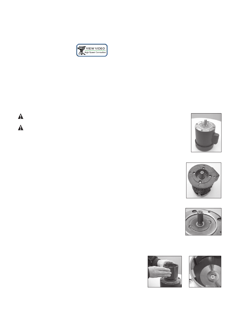
2. Place motor on the fan end. For 56C/145TC and
B5 frame motors go to step 4. See figure 1.
3. For 184 NEMA and IEC motors only - Install the motor
adapter flange (item 14) on the motor face using bolts,
lock washers and flat washers (items 25, 26, 27). See figure 2.
NOTE: Apply anti-seize compound on threads of the bolts.
Torque bolts to the following:
• 80 frame (M6)
=
90 in-lb (10.2 N-m)
• 90/100/112 frame (M8) =
130 in-lb (14.7 N-m)
• 184 NEMA (1/2”)
=
480 in-lb (54.3 N-m)
4. Coat the motor shaft with anti-seize compound. Insert key
supplied with motor into keyway on motor shaft. See figure 3.
NOTE: Make sure the motor shaft is clean and free of burrs.
The outer drive is precision machined and has a bore tolerance of +.0005/-0 inch.
5. Slide the outer drive magnet assembly (item 13) onto the motor
shaft until the motor shaft contacts the snap ring in the bore
of the drive. Figures 4 and 5.
6. Secure the drive on the motor shaft.
Figure 1
Figure 2
Figure 3
Figure 4
Figure 5
6