Finish Thompson SP11/15 SERIES SELF-PRIMING User Manual
Page 16
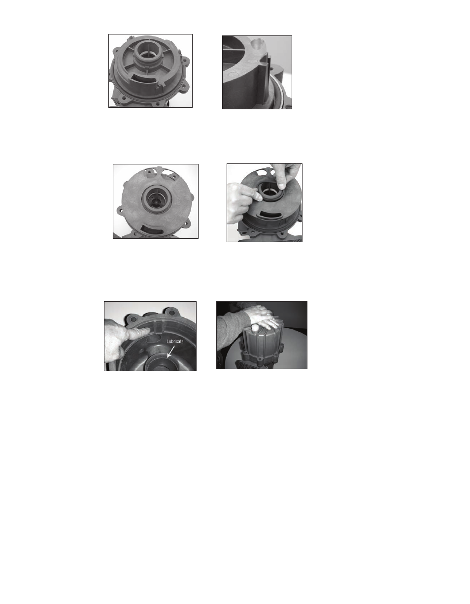
12. Install the separator plate (item 4) by lining up the bottom opening of the inner volute with the opening in the
plate. Line up the slots in the separator plate with the notches in the inner volute. See figure 49.
13. Lubricate the inner volute o-ring (item 5) with a chemically compatible lubricant and install in the groove on the
round suction nozzle in the center of the inner volute. See figure 50.
14. Lubricate the inside of the gooseneck. See figure 51. Install the housing (item 1). Line up the tab on the top of the
separator plate with the notch in the housing (located inside the front of the housing near the discharge port). See
Figure 51. Using uniform pressure, press the housing and barrier into place until it is flush with the motor adapter.
See figure 52.
Figure 47
Figure 48
Figure 49
Figure 50
Figure 51
Figure 52
16
Note:
The fit is tight due to inner volute o-ring. Make sure o-ring is lubricated.
Install the housing bolts, lock washers and flat washers (items 16, 17, 18). Tighten all bolts evenly using a star pat-
tern. Tighten to 20 foot-lbs (27 N-m).
15. Reinstall the pump on the motor/drive magnet following instructions found in “Assembly, Pumps without Mo-
tors,” steps 7-10.