Finish Thompson SP11/15 SERIES SELF-PRIMING User Manual
Page 11
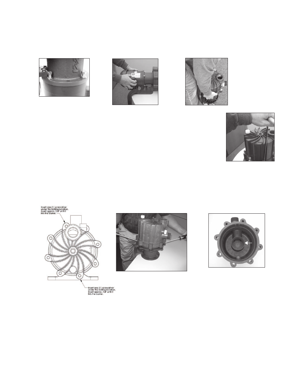
prior to opening the pump. Allow the pump to reach ambient temperatures prior to performing maintenance.
2. For pumps with motors 2 horsepower (1.5 kW) or smaller, securely clamp the pump feet to the bench. Remove
the (4) bolts, lock washers and flat washers (items 22, 23, 24 ) securing the pump to the motor. See figure 9
Firmly grab the motor and pull straight back to disengage the motor and pump. See figure 11
Figure 11
Figure 12
Figure 14A
Figure 13
Figure 15
Figure 9
12
For pumps with motors 3 horsepower (2.2 kW) or larger, place the pump and motor on the
floor. Remove the (4) bolts, lock washers and flat washers (items 22, 23, 24) securing the
pump to the motor. Make sure the motor is on the fan end with the pump facing up. Pull
straight up to remove the pump from the motor. See figure 12.
3. Place pump on bench with housing (item 1) facing up. Using an 8 mm hex (Allen) wrench,
remove (8) 10 mm socket head cap screws, lock washers and flat washers (items 16, 17,
18). See figure 13.
4. Remove the housing by carefully inserting two flat head screwdrivers at the locations
shown in figure 14. Slide the screwdrivers in at the bolt holes between the metal clamp ring
(item 12B) and the housing until they stop. Applying equal pressure, gently pry both screwdrivers in an upward
motion away from the work bench (to avoid damaging sealing surface on the housing). See figure 14A. Housing
is tight due to o-ring seal on the internal “gooseneck.” NOTE: Do not twist the screwdrivers or damage may oc-
cur to the housing. Lift the housing straight up to remove.
Figure 14
5. Examine the housing for signs of wear or damage. Inspect “gooseneck” for cracks. See figure 15. Inspect suction
and discharge for cracks. Inspect fill and drain plug o-rings (item 3A) for chemical attack, swelling, brittleness,
cuts, etc.
6. Carefully remove the inner volute o-ring (item 5). See figure 16. Inspect for chemical attack, swelling, brittleness,
cuts, etc.
7. Pull the separator plate (item 4) off the inner volute (item 6). See figure 17. Inspect for damage and cracks.
8. To remove the inner volute, pull back on the (3) snap fit prongs one at a time so that the hook portion falls into the
channel on the inner volute. See figure 18.