Finish Thompson SP11/15 SERIES SELF-PRIMING User Manual
Page 13
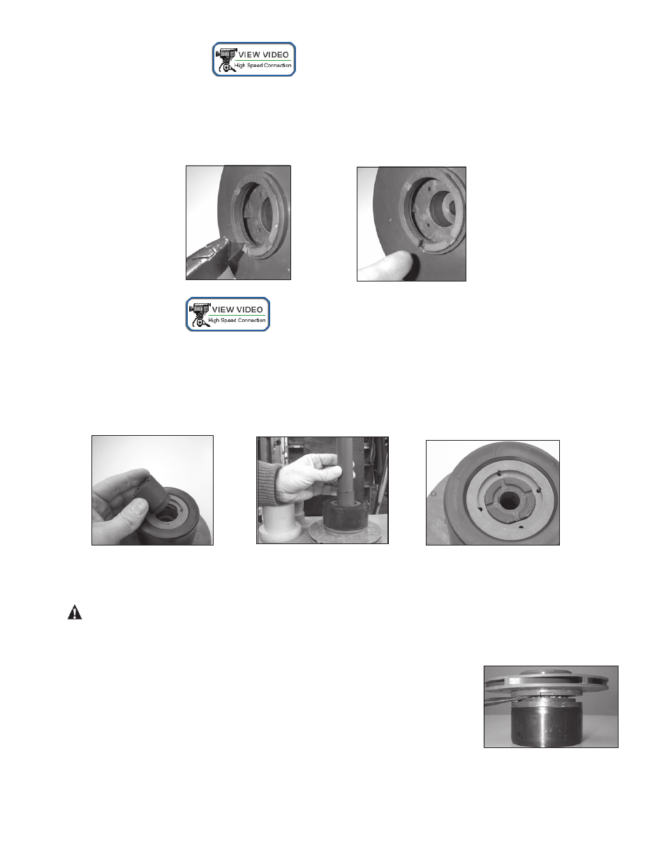
Thrust Ring Replacement
1. Thrust ring (item 7A) is held in-place with a snap fit with a ridge. Using a razor knife or side cutters, cut a notch
out of the thrust ring. Pull ring up and out of the holder. See figures 25 and 26.
2 To reinstall, align the two flats on the thrust ring with the flats in the bore of the impeller. Using a piece of wood
press into place using an arbor press until the thrust ring is completely seated in the impeller.
Bushing Replacement
1. To remove the bushing, place the impeller/inner drive assembly in an arbor press. Insert a 3/4” diameter plastic or
wood shaft through the eye of the impeller and press the bushing out.
2. To replace the bushing (item 8A), place the top of the impeller on an arbor press with the thrust ring face down.
Insert the front of the bushing (figure 27) into the center of the impeller/inner drive magnet assembly, aligning the
flat on the bushing with the flat in the bore of the inner drive magnet. Using a soft arbor, press into place until the
bushing reaches the shoulder molded into the inner drive (figures 28, 29).
Impeller Replacement
CAUTION: Do no damage the outer surface of the inner drive magnet during impeller replacement.
Using the two slots provided, insert a flat blade screwdriver into them and pry the impeller (items 7A, 7) up from the
body of the inner drive magnet (items 8, 8A). Once a gap has been established, work around the perimeter to evenly
increase the gap until the impeller can be removed. See figure 30.
To install a new impeller, place the inner drive magnet assembly face up (splines
facing up) on an arbor press. Align the spines in the impeller with the ones in the
bore on the inner drive magnet. Place a piece of wood over the top of the impel-
ler thrust ring. Using an arbor press, push down on the impeller until it is com-
pletely seated in the inner drive.
Figure 25
Figure 26
Figure 27
Figure 28
Figure 29
Figure 30
13