Finish Thompson SP11/15 SERIES SELF-PRIMING User Manual
Page 12
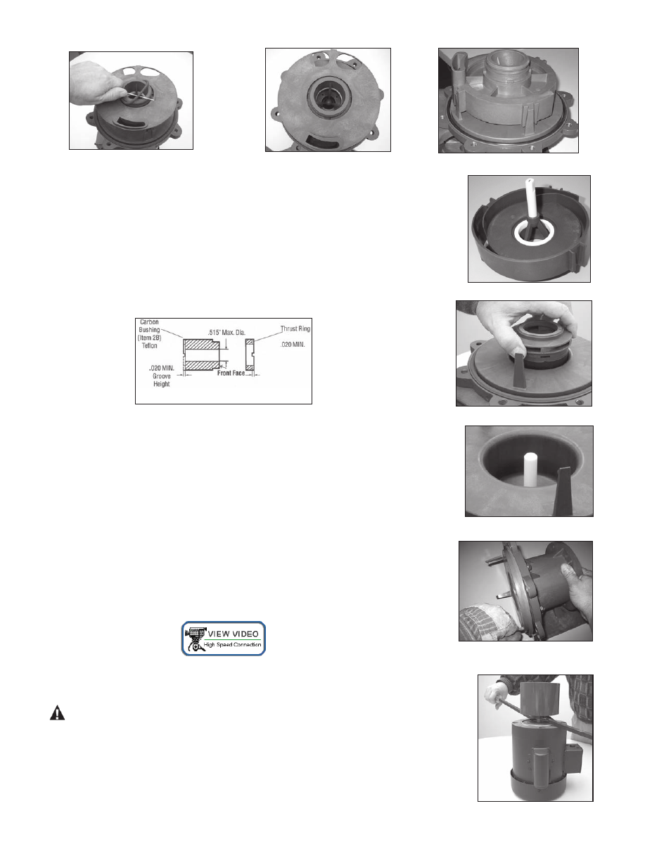
Figure 16
Figure 17
Figure 18
9. Pull the inner volute straight off. Be careful, the impeller shaft may come out
with the inner volute. See figure 19. Inspect inner volute for signs of wear or
damage. Look for signs of rubbing or cracking on the ring or damage to the front
shaft support.
10. Remove impeller/inner drive assembly (items 7A, 7, 8, 8A). Inspect impeller and
drive for signs of wear or damage. Look for signs of rubbing, damage and wear
to the impeller and inner drive. See figure 20. Check the impeller thrust ring and
bushing for wear.
See figure 21.
11. Remove the impeller shaft (item 9) from the barrier or inner volute and check
for signs of cracking, chipping, scoring or wear. See figure 22.
12. Remove the barrier (item 11) from the motor adapter (item 12) (make sure
the impeller shaft has been removed). Pull on one of the three prongs to remove
the barrier. Note: Prongs are sharp. Use a glove or rag for better grip. Inspect the
inside and outside of the barrier for signs of rubbing. See figure 23.
13. Remove the o-ring (item 10) from the barrier and inspect for chemical attack,
swelling, brittleness, cuts, etc.
14. Visually inspect the outer drive (item 13) for rubbing, damage, corrosion or loose
magnets.
Outer Drive Replacement
1. Remove the setscrews (item 13A) from the side of the drive (NEMA motors) or
the bolt, lock washer and flat washer (items 19, 20, 21) from the center of the
drive (metric motors).
WARNING: Be careful, tools will want to be attracted to the magnets.
2. Remove the drive magnet from the motor shaft by gently
prying up from the bottom of the drive. See figure 24.
3. To reinstall the drive or a new drive follow the instructions from
Section I - Assembly, Pumps without Motors, Steps 4-6.
Figure 19
Figure 20
Figure 21
Figure 22
Figure 23
13
Figure 24