Finish Thompson SP11/15 SERIES SELF-PRIMING User Manual
Page 15
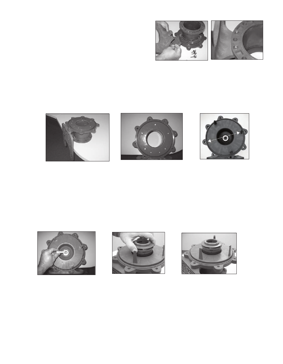
7. Install the barrier (item 11) into the clamp ring (item 12B). Line up the prong that has no prong opposite it with
the 2 o’clock housing bolt hole in the clamp ring. See figure 43A. NOTE: Leave the barrier loose in the clamp
until installing the housing (item 1) to make sure the bolt holes line up.
8. Install o-ring (item 10) in groove in barrier. Make sure it is tucked in all the way around. See figure 44.
9. Install impeller shaft (item 9) into barrier by aligning the flats on the shaft with the ones in the barrier. Make sure
it is completely seated. See figure 44
10. Carefully install the impeller/inner drive assembly (items 7A, 7, 8, 8A) by sliding it over the impeller shaft in the bar-
rier. It is normal for the impeller/inner drive to pop up a slight amount due to magnetic forces. See figures 45 and 46.
11. Install the inner volute (item 6) by lining up the prongs of the barrier with the channels in the inner volute. Press
down evenly until the prongs snap onto the surface of the inner volute. See figures 47 and 48.
5. For 56C, 145TC and 80 frame B14, re-install the plastic
foot (item 15) to the motor adapter (item 12D). Use the
longer M6 bolts, lock washers and flat washers (items 28A,
29 and 30) for the front bolt holes towards the clamp ring.
See figure 40. Use the shorter M6 bolts, lock washers and
flat washers (items 28, 29 and 30) for the rear bolt holes
towards the motor face. NOTE: Nuts (item 31) are glued
into the rear of the motor adapter to help with the installa-
tion of the rear bolts. Make sure the nuts are still in place.
See figure 41. Tighten bolts to 5 ft-lbs. (6.8 N-m). For 184 frame, IEC 90, 100/112 frame B14 and 80/90 frame
B5, leave the foot off until the motor adapter is installed on the motor. This will allow easier access to the bottom
bolt hole in the motor adapter.
Figure 41
6. Position the motor adapter assembly on a flat surface. If the foot is installed, allow the feet to hang over the edge.
see figure 42. Install the o-ring (item 12A) into the groove on the clamp ring. Lubricate the o-ring with a compat-
ible lubricant. See figure 43.
Figure 42
Figure 43
Figure 44
Figure 45
Figure 46
16
Figure 43A
Figure 40