Remote heads – installation instructions – Emergi-Lite Surface Mounted EF10D Series User Manual
Page 2
Emergi-Lite
Tel: (888) 552-6467
Fax: (800) 316-4515
www.emergi-lite.com
10/12 750.1694 Rev. A
Remote heads – Installation instructions
1/1
Emergi-Lite
Tel: (888) 552-6467
Fax: (800) 316-4515
www.emergi-lite.com
10/12 750.1694 Rev. A
1/1
Remote heads – Installation instructions
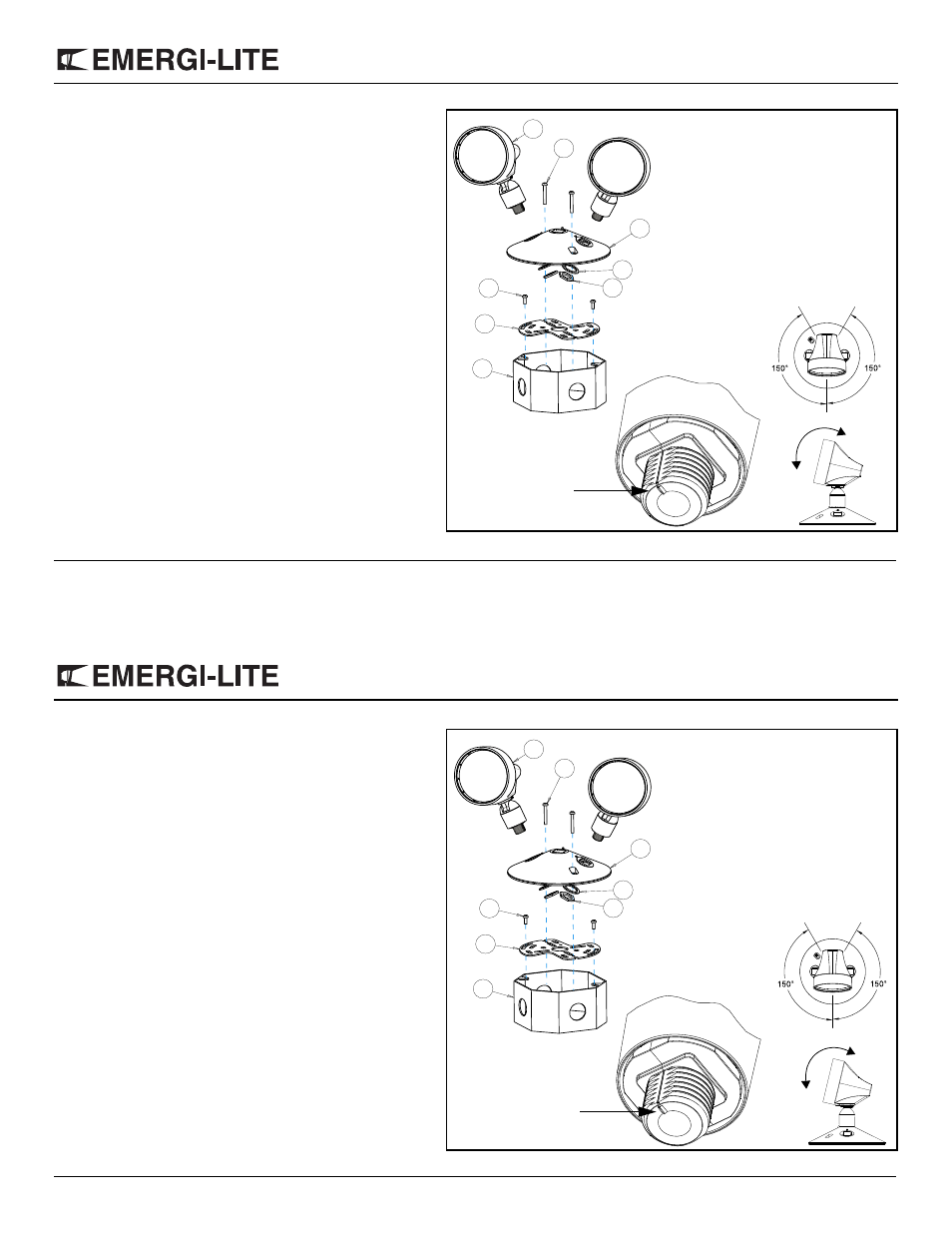
Installation instructions
Note: Lamp heads may already be attached to the canopy.
1. Determine the final position for the lamp heads.
2. Look for the mark on the threaded portion of the swivel to
find the center of rotation for the lamp head.
3. Insert the square surface from the swivel into the square
hole on the canopy ensuring that the center of rotation is as
close as possible to the final position. Secure the lamp head
in place with the lock washer and nut provided.
4. Adjust the heads into there final position.
5. Install the spider plate to the junction box using the junction
box screws.
6. Make the proper connections. The fixture is designed for 6,
12 or 24 VDC (see the lamp voltage indicated on the inside
surface of the canopy). Connect the lamp wires to the DC
supply wires.
7. Use the canopy screws to fix the canopy to the spider plate.
Adjust the lamp head:
Rotation: hold the lamp head and turn it to either side.
-Note: The lamp head can be rotated 150° to either side.
Tilting: hold the lamp head and tilt it up or down.
The lamp head uses a ratchet type mechanism that moves it in
10 degree increments (see fig. 1).
1
2
3
4
5
6
7
8
Parts List
1.
Lamp heads (2 or 3)
2.
Canopy screws
3.
Canopy
4.
Lock washer
5.
Nut
6.
Junction box screws (not provided)
7.
Spider plate
8.
Junction box (not provided)
Figure 1
Rotation
Tilt
Center of rotation