Prestige series - edge-lit led exit series, Self powered models, Maintenance – Emergi-Lite Prestige X40 Edge-Lit Series User Manual
Page 2
Prestige Series - Edge-Lit LED Exit Series
Emergi-Lite
Tel: (888) 552-6467
Fax: (800) 316-4515
www.emergi-lite.com
07/09 750.1436 Rev. A
2/2
Exit panel installation (Figure 1)
1. Remove the exit panel form its carton, do not remove the protective
sleeve until the installation is complete.
2. Partially remove the protective sleeve at the top of the exit panel.
Push the exit panel, with the clips, into the slot in the trim plate
assembly until it snaps. Gently try to pull out the panel to ensure that
it is engaged in the trim plate assembly. Remove the protective
sleeve.
3. Energize AC circuit. Legend and green pilot indicator (self-powered
models), will illuminate.
Important: the Exit panel can only be removed by lowering the trim plate
and pushing on the end clip located on the opposite side of the test
switch with a screwdriver.
Self Powered models
Manual testing (Figure 6)
Press test switch. Legend will flicker then will remain lit. On release,
external green LED will illuminate, and automatic charger will restore
battery to full charge.
Automatic testing and diagnostics (optional)
The models with the automatic testing and diagnostic option include a
micro-controller which tests the unit on a monthly basis and identifies as
well displays failures of the electrical components: battery, charger cir-
cuit, LED lamps.
Self-test
The self-test is performed every 30 days for 30 seconds, every 60 days
for 30 minutes, and annually for 90 minutes.
Diagnostic function (Figure 6)
The diagnostic function uses the pilot light LED indicator. Service is
required if the green LED changes color to red indicating that an alarm
condition is detected.
Maintenance
None required. Models equipped with batteries: if AC supply is to be dis-
connected for 2 months or more, the battery must be disconnected (Self-
Powered Models only).
Note — For safety reasons Nickel Cadmium batteries are shipped dis-
charged. The unites may require 10 minutes of connection to AC supply
before start-up test procedure, and two to seven days to reach full
charge.
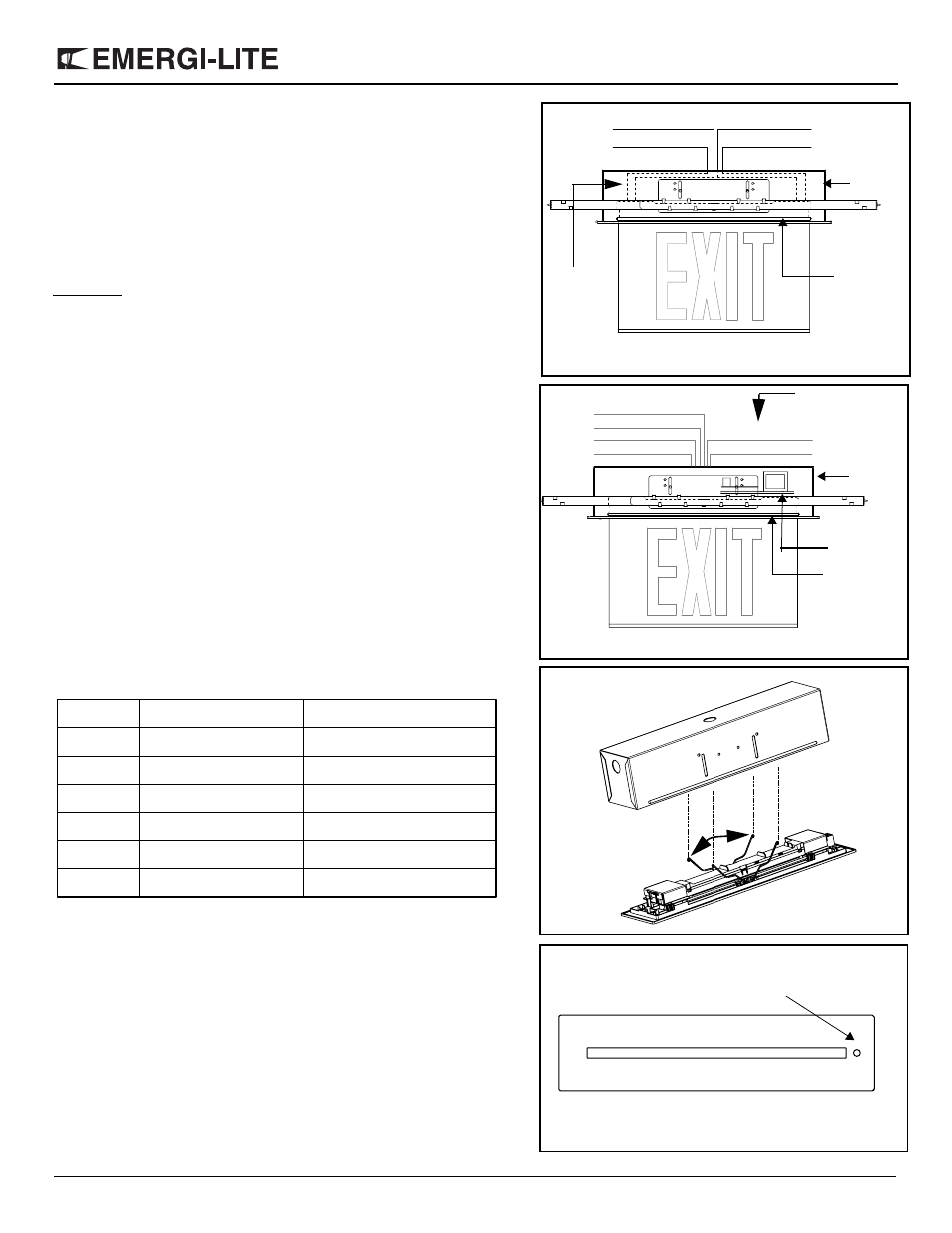
Figure 3
(Regular models)
Blue - DC
Red + DC
Purple AC
White neutral
LED Strip
Back box
DC wires
for remote
DC supply
Figure 5
Figure 4
Transformer
Orange 277VAC
Red 347VAC
Black 120VAC
White neutral
Red + Fire Alarm
Blue - Fire Alarm
LED Strip
Back box
DC wires for
Fire alarm input
(Optional)
(Models with diagnostic feature)
Figure 6
AC Pilot light / Test switch
Trim plate
Diagnostic light (optional)
LED Lamp Failure
Charger Failure
Battery Failure
Battery Disconnect
Auto Test
Normal (AC On)
Four Blinks
Two Blinks
One Blink
Steady on
Blinking
Steady
Red
Red
Red
Red
Green
Green
Pilot light
Status
Diagnostic