Prestige series - edge-lit led exit series – Emergi-Lite Prestige Edge-Lit Series User Manual
Page 3
Prestige Series - Edge-Lit LED Exit Series
Emergi-Lite
Tel: (888) 552-6467
Fax: (800) 316-4515
www.emergi-lite.com
05/12 750.1421 Rev. C
3/4
c. Re-install the electronic module and the bracket, this time ori-
ented as in (Figure 5c). For units with transformer: reconnect the
transformer harness to the electronic module.
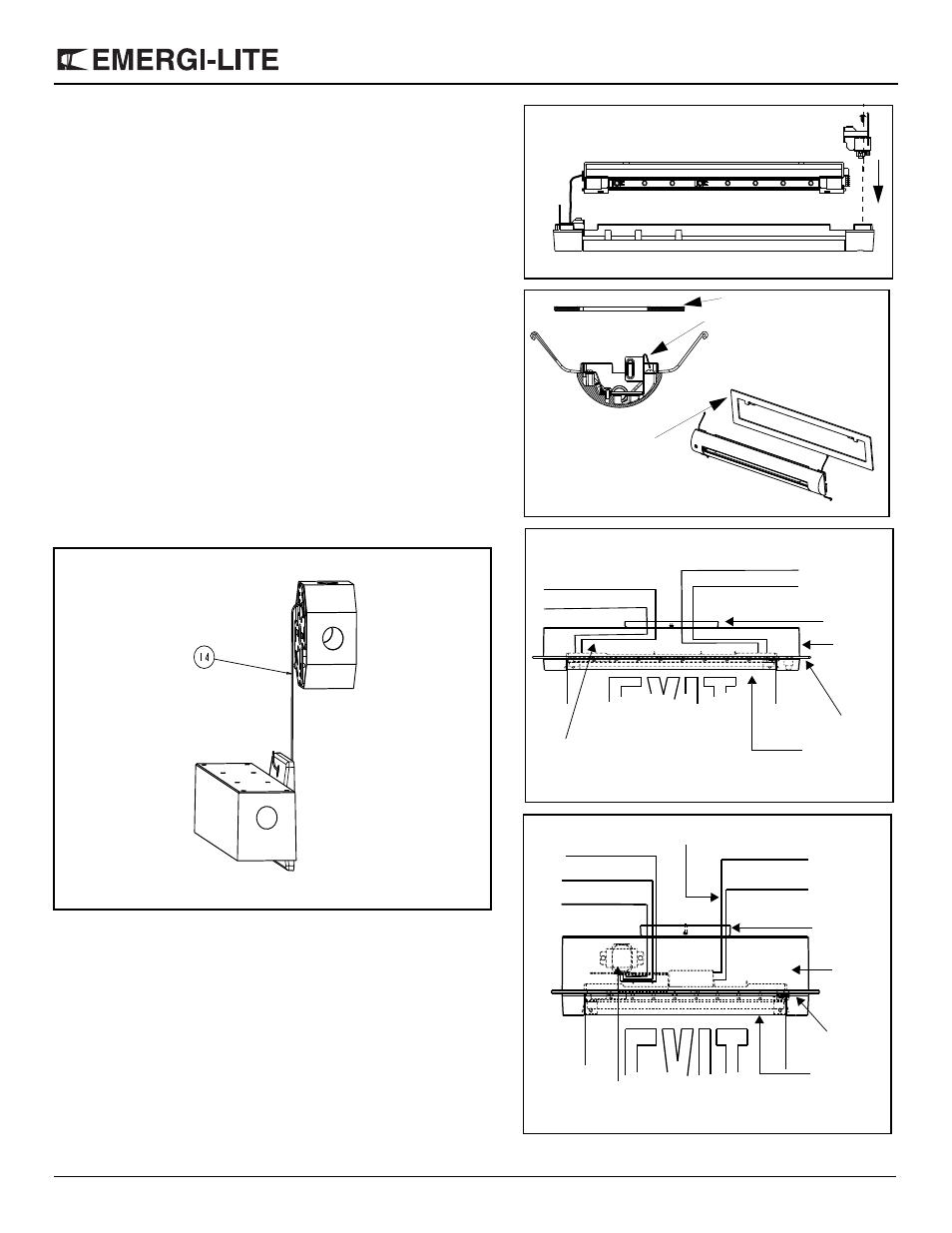
3. Recessed installation (Figure 6). Attach the flat trim ring to the trim
plate. Orient the trim ring and snap it with the two tabs behind the
hooks of the side brackets.
4. Electrical connection (Figures 8,9)
a. Connect the long ground lead with eyelet from the back box to
the trim plate assembly with the hardware provided
b. Make the proper connections. The system can accept input volt-
ages of 120 VAC to 347 VAC. For regular models connect the
purple (hot) and white (common) leads to the building utility (Fig-
ure 8). For models with diagnostic feature connect the white
(common) and black (120 VAC) or orange (277 VAC) leads to
the building utility (Figure 9).
c. For remote power DC unites, connect the red wire to the positive
of the DC supply and the blue to the negative (6 to 24 volts).
5. Take the trimplate assembly and connect the harnesses together
with the back box mating colors .
6. Compress the retention springs and insert the trim plate assembly
in the back box. Align the trim plate assembly flush with the back
box, wall or ceiling as installed..
Figure 5c
Trim ring tab
Hook on trim plate assembly
Trim ring tab this side
Figure 6
Figure 8
(Regular models)
Blue - DC
Red + DC
Purple AC
White neutral
Canopy
LED Strip
Back box
Trim plate
DC wires for
remote DC supply
Figure 9
(Models with diagnostic feature)
Transformer
Black 120VAC
White neutral
Red + Fire Alarm
Blue - Fire Alarm
Canopy
LED Strip
Back box
Trim plate
DC wires for
(Optional)
Fire alarm input
Orange 277VAC
Figure 7
Note:
The hook is used for
surface mount units only.