Premier series - thermoplastic led combo sign, Unit testing, Manual testing – Emergi-Lite Premier Series Thermoplastic Combination Battery Unit and Exit Sign User Manual
Page 2: Automatic testing and diagnostics
Premier Series - Thermoplastic LED Combo Sign
Emergi-Lite
Tel: (888) 552-6467
Fax: (800) 316-4515
www.emergi-lite.com
03/10 750.1401 Rev. C
2/2
hole plug(5). Feed AC supply leads (and DC leads for remote lamps if
applicable) out through top opening and then through canopy. Remove the
canopy lock(12). Snap the canopy into the opening on top of frame. Rein-
stall the canopy lock into the canopy. Secure the assembly with canopy
housing screw(11) (See Fig. 1). Make the proper wire connections. The
“Quick-install” canopy is equipped with ribs allowing you to hang the unit
spider plate to facilitate wiring (See Fig.4). Feed the excess wire into the
junction box. Unhook unit and slide ribs on canopy into designated
notches on the spider plate (See Fig. 4). Secure the canopy to the junction
box using the canopy screws provided(10).
6. Install battery(s) and wires.
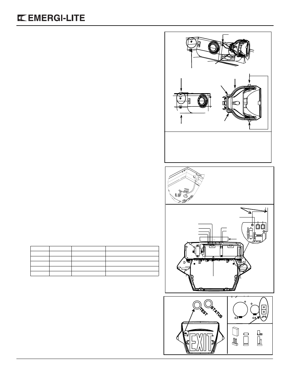
7. Remove the appropriate chevron(s) on the exit door by holding sign with both
hands. Push chevrons from the inside with thumb (See Fig. 2). You will need to
unsnap the diffuser panel to do so.
8. Connect battery “T Connector” to PCB (“B” connection) (See Fig. 6
).
9. Remote lamp(s) connection : Feed external DC+ & DC- wires through unit and
connect to internal wires using wire nuts provided (See Fig. 6).
10. Reinstall combo door(s). Fasten screws (only for some models).
11. Remove lenses (See Fig. 3) and discard plastic bags. Adjust the lamps in
appropriate position. Re-install both lens.
12. Energize AC. Sign will illuminate.
Note — DC input voltage is 6 or 12 volts depending on unit type.
Unit testing
Manual testing
Press test switch. Legend will flicker, but remain lit. On release, external green
LED will illuminate, and automatic charger will restore battery to full charge.
Automatic testing and diagnostics
The automatic testing and diagnostic function includes a micro-controller which
self-tests the unit on a monthly basis and identifies as well displays failures of the
electrical components: battery, battery charger, lamps, LEDs.
Self-test
The self-test is performed every months for 1 minute, every 6 months for
30 minutes, and annually for 90 minutes.
Diagnostic function
The diagnostic function uses an external green LED indicator. Service is
required if the green LED blinks indicating that an alarm condition is
detected (See Fig. 7).
For Nexus models, refer to “Nexus addendum”.
Units with automatic testing are shipped “non-audible”. If you wish to make the unit
“audible” simply re-orient the jumper “JP5” as shown in figure 8.
Maintenance —
None required. If AC supply to the unit is to be disconnected for
2 months or more, the battery must be disconnected.
Note — NiMH (Nickel Metal Hydride) batteries are shipped discharged and need
to be connected to an AC supply for 10 minutes before start-up test procedure, 24
hours to charge to meet a 30 minute discharge or 96 hours to reach full charge.
o
Green
Steady On
AC On
o
Red
Steady On
Battery Disconnect
-o
Red
Blinking
Battery Failure
o-o
Red
Two Blinks
Charger Failure
o-o-o
Red
Three Blinks
Lamp Failure
o-o-o-o
Red
Four Blinks
LED Failure
Support
Stopper
Stopper
Arrow on Central housing
points towards the “front side”
“Back side” of unit
Apply pressure here
when handling
No Stopper
(Facing “Back side” of unit)
Lamp wire groove
Figure 5
Feed Wires Through Plastic
Conduit (Wall Mount Only)
120 VAC Black
White Neutral
Ground
Blue - DC
Red + DC
DC +
DC -
Canopy
Remote DC Supply
DC Wires for
La
m
p
1
La
mp 2
Lamp 2
Batteries
Figure 6
Battery
L+
L-
Transformer
LED Strip
277 VAC Orange
Lamp 1
B
Remote lamp connections
L-
Assembly steps:
1.
Remove lamp assemblies from plastic wrapping.
2.
Place wires in respective grooves on the central housing.
3.
Align and snap in place with "stopper" oriented per Figure 5.
4.
Handle assemblies by applying a pressure on either end of the
support per Figure 5.
Test Switch
External Green LED
Figure 8
Figure 7
JP5
non-audible
audible