Svxh series – class i, div 2 combo unit – Emergi-Lite Survive-All SVXH Series User Manual
Page 2
SVXH Series – Class I, Div 2 Combo Unit
2/2
Emergi-Lite
Tel: (888) 552-6467
Fax: (800) 316-4515
www.emergi-lite.com
12/08 750.1377 Rev. B
b. Route unswitched AC circuit wires into the housing through conduit.
c. Reinstall the electronic module inside the housing using the four
screws.
Junction Box Entry
a. Remove appropriate knock-outs on back plate for installation on junc-
tion box (see figure 3).
b. Route unswitchd AC circuit wires into the housing through large hole
in back plate.
c. Install the unit on the junction box (Rated for Class1 Div 2) with the
junction box screws.
d. Reinstall the electronic module inside the housing using the four
screws.
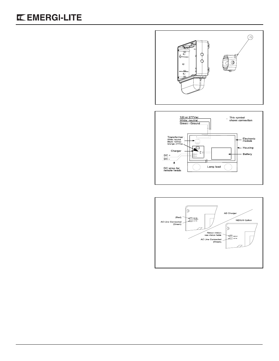
2. ELECTRICAL CONNECTIONS
Auto-diagnostic models (refer to figure 4
.
):
a. Connect transformer primary wires to AC wires from building: white
wire with neutral; black (120Vac) or orange (277Vac) to line voltage.
Unused primary wire must be insulated to prevent shorting. Connect
green wire to the ground.
b. Reconnect the lamps on terminal blocks (L1+/L1-).
c. For units with remote capacity, connect the remote heads DC+ to L1+
and DC- to L1-.
d. Connect the battery to the charger board.
Nexus models:
See Nexus addendum for the details on electrical connection.
3. Lamps adjustment:
a. To access the lamps, remove the lens. Remove the lamps protec-
tors. Adjust the lamps in appropriate position. Put the lens back in
place.
4. Put the unit cover back in place. Make sure the unit is tightly
closed.
5. Energize AC.
Manual Testing
Operate the magnetic “test switch” by holding the provided magnet where
indicated near the LED display (see figure 5). This will initiate a one minute
test. The DC lamps will illuminate for approximately one minute, then the
unit will automatically return to stand by mode. Test can be cancelled by
holding the magnet near the test switch again.
Automatic Testing
The unit will perform an automatic self-test of 1 minute every month,
10 minutes every 6 month and a 30 minutes self-test once a year.
Automatic Diagnostics
There are five diagnostic indicators: one external and four internal. Unit must
be opened to gain access to internal indicators.
External: Servicel alarm, “Service Required”. The LED will turn-on if any
alarm condition is detected (see fig. 5).
Internal: Battery Failure, Battery Disconnect, Charger Failure & Lamp Fail-
ure. Steady ON if alarm condition exists.
Normal operation, No fault — “Service Required” is OFF.
Faulty operation — “Service Required” is ON.
(see AD charger owner manual for more details)
Nexus models
Nexus models use two local indicators. One is a green LED for AC pilot lamp.
The other is a bicolor LED (Service) which identifies and displays the Nexus
status. See Nexus addendum for details.
15
Figure 3
Figure 4
Figure 5
Service Alarm