120v, 277v – Emergi-Lite Survive-All SV Series User Manual
Page 3
SV Series – Survive-All
3/4
Emergi-Lite
Tel: (888) 552-6467
Fax: (800) 316-4515
www.emergi-lite.com
10/13 750.1518 Rev. B
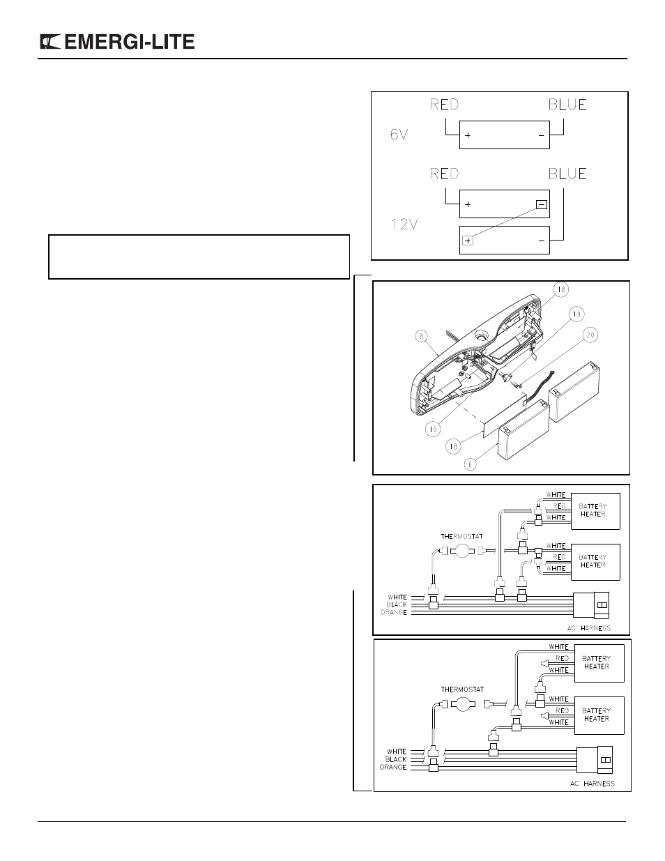
b. Refer to figure 8 for 120VAC input voltage and to figure 9 for
277VAC . Use wire taps provided with the hardware kit to connect
battery heater. Unused wires must be insulated to prevent short-
ing.
c. Re-install the batteries. Battery heater is placed between the bat-
tery and the backplate. See figure 6 for battery
wiring diagram.
Re-install the electronic module as shown on figure 5.
d. Connect transformer harness to AC harness.
7. For unit with remote capacity, connect remote heads to termi-
nal L+ and L- (see figure 11).
Calculation of total allowable remote capacity of unit:
Maximum remote lamp power = unit capacity minus the total power of
lamps included with unit.
8. Snap electronic module on backplate.
9. Adjust lamp aiming.
10.Install the lens by using the 6 tamper-proof screws (1). To
insure water tightness, gasket screws (x6) have to be installed
from the inside (see figure 3). Tighten the screws approxi-
mately 5 Lb.-Ft. DO NOT OVER TIGHTEN.
11. For food processing areas, in order to avoid food accumula-
tion, screw caps have to be installed (provided with the hard-
ware kit).
12.Energize AC. Lamps will turn on for few minutes.
13.See page 4 for testing procedure.
Nexus:
For connections related to Nexus system, refer to Nexus Adden-
dum.
Figure 6
Figure 7
Figure 8
120V
Figure 9
277V
FOR C
O
LD
WEA
T
HER
O
P
TI
ON ONL
Y