Provider series - emergency lighting, Unit testing, Maintenance – Emergi-Lite Provider PRO-2N/PRO-3N Series User Manual
Page 2
Provider Series - Emergency lighting
Emergi-Lite
Tel: (888) 552-6467
Fax: (800) 316-4515
www.emergi-lite.com
02/14 750.1705 Rev. C
2/2
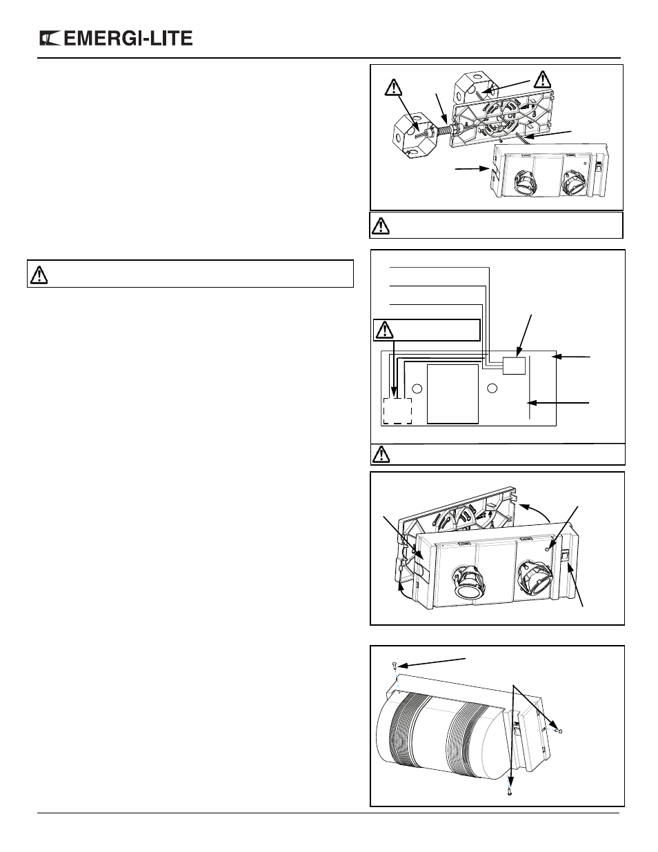
d. Line cord installation (option)
Mount the backplate to the wall. Install the strain relief (see fig. 3b). Using
pliers, crimp strain relief onto the line cord. Keeping pressure on the pliers,
insert the strain relief into the pre-drilled hole on the housing.
7. Make the proper connections. The system can accept input voltages of 120/
277 VAC (see fig. 4).
120 VAC — Connect the black (120 VAC) and white (neutral) leads to the
building utility. Insulate the unused wire.
120 VAC with line cord (optional) — Before making the connections, fol-
low the line cord installation instruction in section 6e. Make the proper con-
nections. Connect the wire with the smooth side from the line cord to the
black (120 VAC) on the unit and the ridged wire from the line cord to the
white (neutral) on the unit. Insulate the unused wire. Connect the green wire
on the transformer (if applicable) or insulate the unused green wire from the
line cord.
277 VAC — Connect the orange (277 VAC) and white (neutral) leads to the
building utility. Insulate the black wire.
Route entry wires to avoid contact with the transformer, battery terminals
and charger PCBA. Refer to figure 4.
8. Connecting external lamps: pass external DC wires into the unit and connect
to internal lamp wires or directly to the PCBA depending on the model.
9. When ready to energize AC circuit, connect the battery.
10. Slide the housing over the tabs; conduit side on housing over conduit side
on backplate (see fig. 5). Assemble the conduit side first, then align the tabs
on the other side of the housing and of the backplate. Press together until it
snaps.
11. Remove the clear lens by prying with a screwdriver, where indicated (see fig.
2).
12. Rotate heads to desired position and replace clear lens.
13. Energize AC. The AC pilot indicator, located under the cover, will illuminate
(see fig. 5).
Vandal resistant (option)
Units with vandal resistant option: there are three vandal resistant screws. Two
are securing the cover, and the other one secures the housing and the backplate
(see fig. 6).
Unit testing
Manual testing
Press test switch (see fig. 5). The emergency lamps will illuminate. When switch
is released, lamps will go off. Allow unit to charge for 24 hours before initial test-
ing.
Automatic testing and diagnostics
The automatic testing and diagnostic function includes a micro-controller which
self-tests the unit on a monthly basis and identifies as well displays failures of
the electrical components: battery, battery charger, lamps.
Self-test
The self-test is performed every month for 1 minute, every 6 months for 30
minutes, and annually for 90 minutes.
Diagnostic function
–For diagnostic function, refer to “User Manual for AD”
–For Nexus models, refer to “Nexus addendum”
Maintenance
None required.
If AC supply to the unit is to be disconnected for 2 months or more, the battery
must be disconnected.
Conduit hole
to knock out
Figure 3d
DC wires
AC wires
White neutral
Black 120 VAC
Figure 3
Orange 277 VAC
Housing
PCB
Transformer
Unused primary wire must be insulated to prevent shorting.
Make all AC connections
on this side of battery
Battery
Figure 5
Assemble conduit
side first
Test switch
AC pilot indicator
Close housing until it snaps
Figure 6
Vandal resistant
screws for
vandal resistant
option
Important: all AC or DC connections must be done in
individual external junction boxes.