Rs series - emergency light unit, Manual testing – Emergi-Lite RS Series User Manual
Page 2
RS Series - Emergency light unit
Emergi-Lite
Tel: (888) 552-6467 ext. 547 or 255
Fax: (888) 867-1565
www.emergi-lite.com
12/07 750.0144 Rev. D
2/3
b. Remove appropriate knock out for AC supply.
c. Slide the hanger bars through the tabs in the adjustment brackets
(see fig. 4) and place the assembly between the framing mem-
bers. Align the back box as required and fasten bars to the fram-
ing members.
d. Align the open surface of box where the finished surface of sheet
rock will be and tighten nuts and studs (see fig. 5).
Suspended ceilings
a. Determine the desired orientation between grid members. Locate
sides of the back box that will be parallel to the longest grid mem-
bers. Mount the adjustment brackets to these sides using the
studs on the brackets and nuts. Do not tighten (see fig. 3).
b. Remove appropriate knock out for AC supply.
c. Slide hanger bars through the tabs in the adjustment brackets
and rest assembly on top of grid members. Notch on bars should
hook over grid member (see fig. 5). Align the back box as
required and fix location by cutting a hole in the ceiling panel and
allowing back box to hang through the panel.
d. Align the open surface of the box flush with the surface of the ceil-
ing panels and tighten the nuts and studs (see fig. 5). Hang the
fixture from the framing above ceiling grid with solid wires, (pro-
vided by others), if required by code.
3. Route AC unswitched circuit of rated voltage into the back box, allow-
ing approximately 6” of wire for connection.
4. If required, extend DC wiring for remote DC fixtures into the back
box.
Note — Wiring must comply with NEC Art, 700 and 720. Do not
exceed rated wattage of unit.
5. Connect DC wiring to load terminals on circuit board marked, “L+ and
L-”.
6. If removed, reinstall battery.
7. Make the proper connections. Our system can accept input voltages
of 120 VAC or 277 VAC (see fig. 6).
120 VAC — Connect the black (120 VAC) and white (Neutral) leads
to the building utility. Insulate orange wire.
277 VAC — Connect the orange (277 VAC) and white (Neutral) leads
to the building utility. Insulate black wire.
8. When ready to permanently energize AC circuit, plug polarized bat-
tery connector into the PC board.
9. Replace cover/electronics assembly.
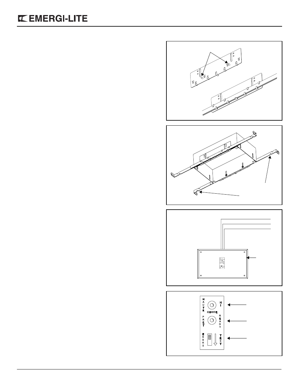
10. Energize AC circuit. Pilot lights will come on. Red indicates that the
charger is on high charge (not present on RSC units). Yellow is an
indication that the AC supply is present (see fig. 7). After the unit has
reached full charge, it is normal for the red light to pulse on occasion-
nally. However, if the red pilot light remains on for more than a week,
it is an indication of a malfunction.
Manual testing
Press test switch (see fig. 7). Lights will illuminate, AC pilot lamp will
extinguish. On release, pilot lamp will illuminate, lights will turn off, and
the automatic charger will restore battery to full charge.
Figure 4
Studs
Figure 5
Notch on bars
should hook over
grid members
black (120)
Figure 6
white (neutral)
orange (277)
cover
electronics
Figure 7
Yellow Pilot
Red, Charge
Test switch