Electronics International CGR-30P User Manual
Page 41
43
Scrn Location – This field places the function at a specific location on a screen. Many of the selections are
for E.I. use only and should never be selected. The following selections can be used:
No-Disp - Not Displayed on any screen. If the Gauge Type is set to anything other than None, this
function will be recoreded in the flight data.
Arc-Left - Main Screen, Left Arc
Arc-Right - Main Screen, Right Arc
Arc-Center - Main Screen, if only one arc gauge at the top of the Main Screen is to be used, select
Arc-Cent.
Main 4 (- 6) - Main Screen, top to bottom horizontal strip gauges are 4 through 6.
Sys-1 (- 3) - Secondary Screen, top to bottom left gauges are 1 through 3.
Sys-4 (-6) - Secondary Screen, top to bottom right gauges are 4 through 6.
Spc Algorithm – This field applies Special Algorithms to the
function such as fuel flow, bar graph, RPM, etc.
Map PW – This field allows E.I. to set the password level
required to produce a map for this function. Maps are normally
used to calibrate Fuel Level functions but they can be used on
any function to calibrate for non-linear input signals.
Map
– This field calls up the Function Mapping screen for a
function. Also, it allows you to edit the Map. The Function
Mapping screen is covered later in this section of the manual.
Edit Probe Cal – This field allows you to change the calibration
settings for the selected Probe. The Probe Calibration screen is
covered later in this section of the manual.
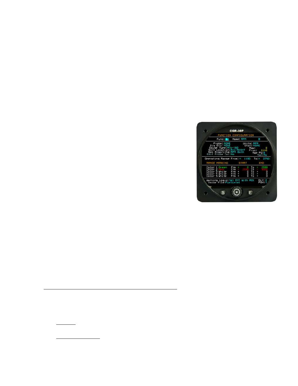
Operating Range (From__To__) - These fields allow you to set the operating range of the Arc or
Horizontal Strip Gauges. Set the “From” and “To” fields approximately 10% below and above the span
between the maximum and minimum operating range. This allows room for the red limit area to show up on
the gauge.
Color 1 to 5 – This row of fields is used to set the range markings for the Arc and Horizontal Strip gauges.
Refer to your aircraft’s POH when setting the Color Ranges. Start with the lowest value and work up to the
highest. FAR 21.1549 requires that the maximum and minimum operating limits be marked in Red, any
precautionary ranges must be marked in Yellow and the normal operating range must be marked in Green.
It is important to adhere to FAR 21.1549 requirements.
Warning Logic – This field sets the operation of the External Caution (yellow) and Warning (red) Lights.
The selections are as follows:
Disabled – This setting disables the external lights for this function.
Both Off with ACK – When a function enters a red or yellow operating range, the appropriate
External Light will blink. This setting turns off both the external red and yellow lights when the blinking
is acknowledged.