Electronics International CGR-30P User Manual
Page 40
42
readouts at the bottom of the screens are also functions (EGT, CHT, EGT-H, CHT-H, EGR-D, CHT-D). Only
the fuel tanks displayed on the Fuel Qtys Screen are not treated as functions.
Warning – Unless you clearly understand the operation of the CGR-30P and how the Function Configura-
tion Screen works, Do Not attempt to change any field in this screen.
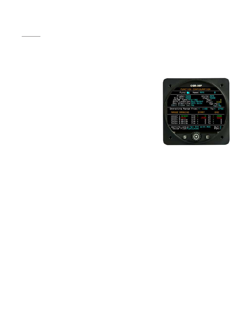
The operation of each field in the Function Configuration Screen is provided below:
Func – This field allows you to select any of the functions currently configured for the CGR-30P. Selecting
the “0” function allows you to develop a new function.
Name – This field allows you to name the function. This is the
name that will be displayed on one of the CGR-30P screens.
Many of the function names are recognized by Special Algo-
rithms and should not be changed.
The maximum displayed
characters are 4 for the arcs and 7 for the horizontal strip gauges.
Probe – The Probe selected in this field pulls in calibration data
that can be edited in the “Edit Probe Cal” screen. Normally the
probe selected matches the probe connected to the EDC. When
a new function is developed, you should use a probe displayed in
blue. Probes displayed in yellow may be used by other func-
tions. If a probe is used by more than one function and the
calibration for the probe is changed, the calibration for all the
functions that use that probe will be changed.
Units – The units displayed in this field are displayed with the function. This is simply a character field, it
does not provide any conversion between units. The units for the value displayed are set by the probe
calibration data.
The displayed units can have up to three characters.
Sig Src – This field sets the source of the signal for this function. The signal can come from one of two
EDC-33’s that may be connected to the CGR-30P or from another internal function. The signal is modified
(or calibrated) by the Probe Calibration settings.
Chan – If the Signal Source is from an EDC, then this Channel field is used to determine what channel on
the EDC the signal is coming from.
Gauge Type – This field sets the type of gauge that will be displaying the function (arc, strip, digital only,
etc.). You should select a gauge type appropriate for the location for which it will be displayed.
Raw and Proc – The Raw data field shows the data as it is received from the Signal Source. The Pro-
cessed data field shows the data for the function after the Raw data has been modified (or calibrated) by the
Probe Calibration settings and any map.