Electronics International CGR-30P User Manual
Page 36
38
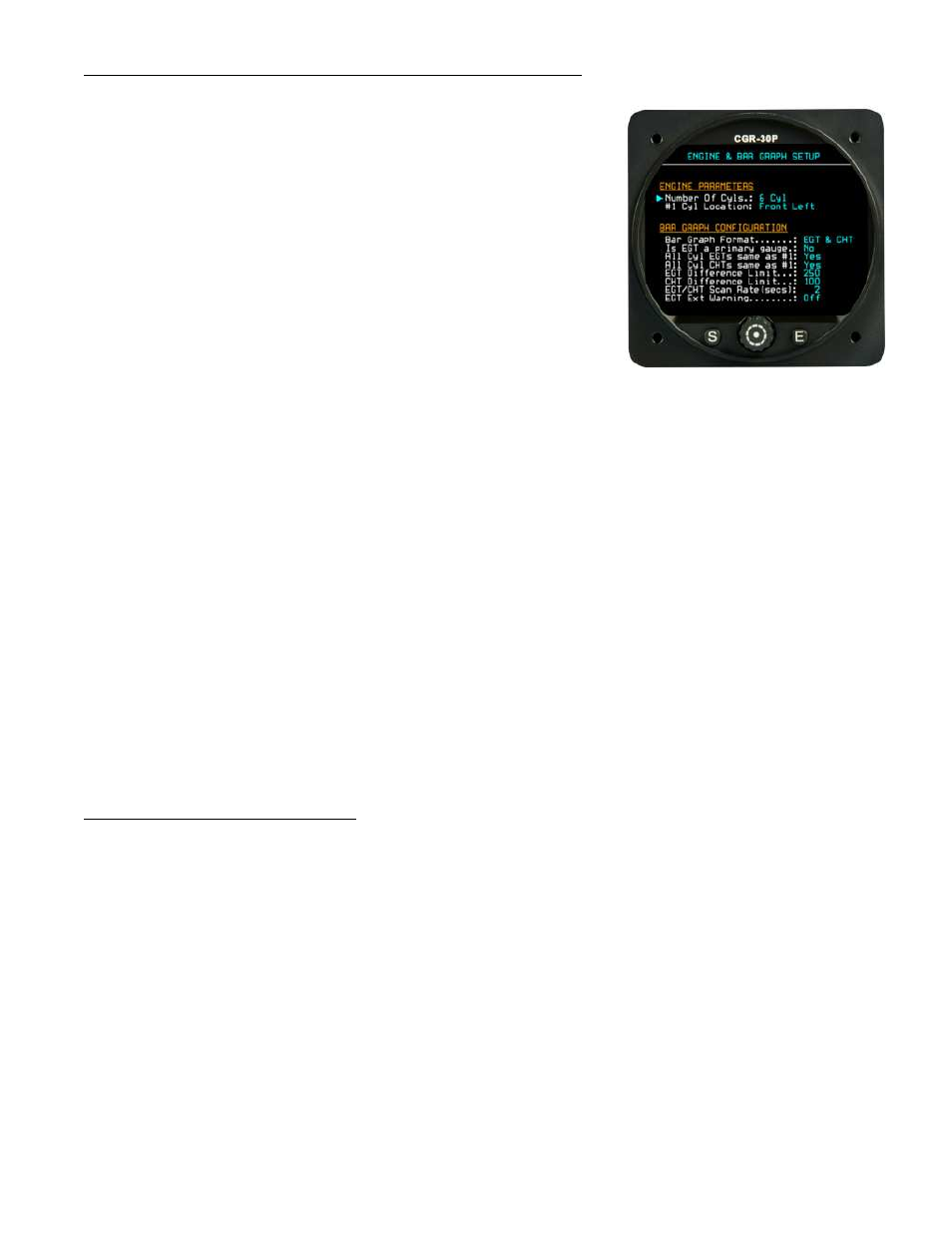
7.6 Engine and EGT/CHT Bar Graph Setup Screen:
The “Engine Parameters” section allows you to set the number of cylin-
ders and the location of the #1 cylinder. This sets the number of bars to
be shown in the Bar Graph on the Main screen. Also, when the engine is
displayed in the EGT or CHT Digital mode, the #1 cylinder will be
shown correctly.
The “Bar Graph Configuration” fields provide the following:
Bar Graph Format – This allows the bar graph to display only
EGTs, only CHTs or both.
Is EGT a primary gauge – If the EGTs are primary, the user
will not be allowed to change EGT limits.
All Cyl EGTs same as #1 – This allows the limits set for cylinder #1 to be used for all the EGT limits.
All Cyl CHTs same as #1 – This allows the limits set for cylinder #1 to be used for all the CHT limits.
EGT Difference Limit – This sets the maximum spread allowed between the EGTs. This parameter also
shows up in a User screen.
CHT Difference Limit – This sets the maximum spread allowed between the CHTs. This parameter also
shows up in a User screen.
EGT/CHT Scan Rate (secs) – This is the rate at which the cylinders are scanned (in the SCAN mode)
and the data is displayed to the pilot. This parameter also shows up in a User screen.
EGT Ext Warning – If this field is set to “On” and an EGT differential or upper limit is exceeded, the
external warning light will blink.
7.7 Fuel Tank Setup Screen:
This screen allows you to setup the fuel tanks for estimating the fuel levels based on fuel flow. Estimated individual
fuel tank levels may be displayed or the Total Fuel on-board may be displayed. There are advantages and disad-
vantage for displaying estimated fuel in each tank versus displaying only the total fuel on-board.