Electronics International CGR-30P User Manual
Page 39
Voice Switch – This is not used at this time.
Port 1 and 2 Loopback Fields – To test a port, connect the Tx pin to the Rx pin. Set the Loopback
Testing field to “Yes.” If the Tx and Rx lines on the port are working properly, the appropriate field will
display “Success” otherwise it will display “Fail.”
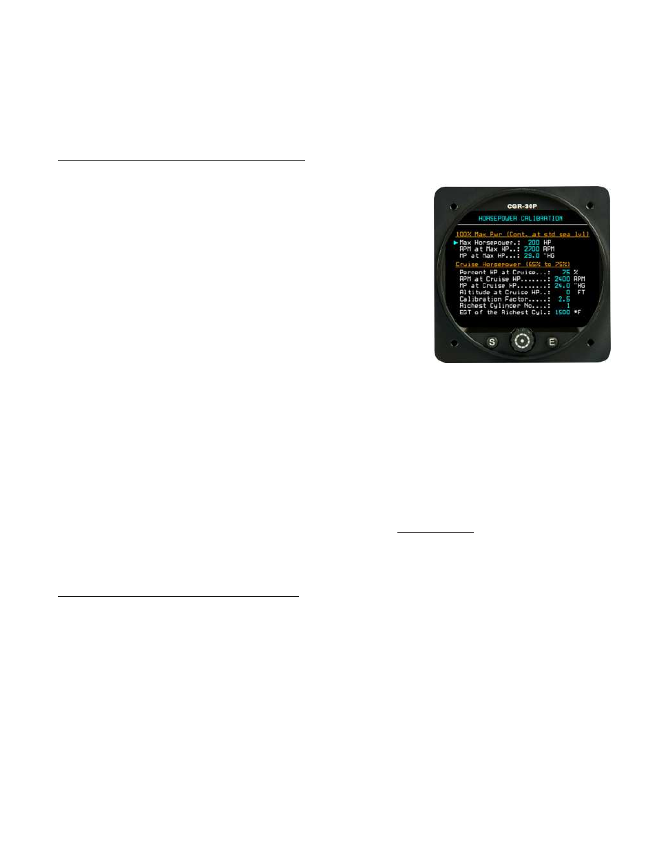
7.10 Horsepower Calibration Screen:
Engine horsepower is calculated from RPM, Manifold Pressure, Altitude
and the Mixture setting. Most of the data is available from engine perfor-
mance charts found in your aircraft’s POH or from the engine manufac-
turer. Some of the data will have to be collected during flight.
“100% Max Power (Continuous at standard sea level)” Section:
Enter the engine data requested in this section from your POH or pub-
lished performance chart for your engine.
“Cruise Horsepower (65% to 75%)” Section: From your engine’s
performance chart, select an RPM, MP and Altitude at which you
normally fly that produces between 65% and 75% horsepower. Enter
the HP, RPM, MP and Altitude data into the appropriate fields.
“Calibration Factor:” The calibration factor corrects the Horsepower calculation at low horsepower settings for
different engines. Set this field to “2.9” for a Continental engine or “2.4” for a Lycoming engine.
“Richest Cylinder No.” and “EGT of the Richest Cyl”: These two fields correct the horsepower reading for
leaning. Lean your engine at the RPM, MP and Altitude listed above. Be sure you do not exceed your engine’s
recommended power requirements for leaning. Use the “Lean-LOP” screen. Note the first cylinder to reach peak
EGT. This is your leanest cylinder. Continue leaning and note the last cylinder to reach peak EGT. This is your
richest cylinder. Enter this cylinder’s number in the “Richest Cylinder No” field. Richen the mixture until the leanest
cylinder once again reaches peak EGT. Enter the EGT reading for the richest cylinder in the “EGT of the Richest
Cyl” field while the lean cylinder is operating at peak EGT.
7.11 Function Configuration Screen:
This screen is used to configure most of the functions displayed on the CGR-30P. A function is each of the param-
eters monitored by the EDC-33P, such as RPM, M.P., Fuel Flow, Fuel Press, Oil Temp, Oil Press, Vac, Volts,
etc. Also, derived functions such as Local Time, Zulu Time, Flight Time, all fuel calculations (Remaining, Used,
Fuel-to-Destination, Time-to-Empty, etc.) are treated as independent functions and are configured in this screen.
The three annunciators on the Secondary and Fuel Screens are also independent functions. The EGT and CHT
41