Teledyne 7120 - NDIR analyzer User Manual
Page 31
3 Start-up and Theory of Operation
Model 7120
3-8
Teledyne Analytical Instruments
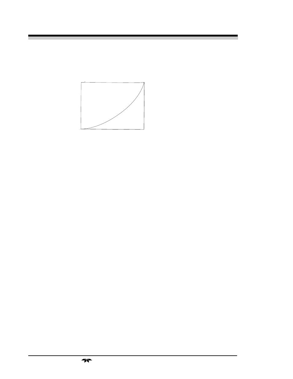
NDIR Bench Output
Figure I
Gas Concentration
Figure II
Linearizer Input
Linearizer Output
to create a linear response. Refer to section 4.3.7 and 4.8.2 to see how
linearizer is programmed.
Piece-wise approximation is the method used to linearize the signal, i.e., the
linearizer’s output to input relationship can be graphed as a number of
straight line segments connected together to approximate the desired curve
that would be required to compensate for the nonlinearity of the bench
The points at which the compensation curve changes slope are called
breakpoints. The slope of each segment corresponds to the gain of the
linearizer in that segment, and this gain has to vary according to the input
voltage. This is achieved through software by adjusting a multiplier factor at
each straight line segment. The linearizer has nine specific voltage segments.
3.7 Control Unit
The Control Unit that controls the zero cycle and the sample system,
which may be common for all other Control Units is called the Slave Control
Unit. The master is unique because it contains the timer PC board and mode
switching programming for operation of any internal/external calibration or
auxillary valving.
The master control unit drives the other control units called slaves. The
slave control unit has all the features of the master except timing and control
of the sample system.
When a system contains the automatic calibration option, all control
units are slaves. The Auto-Cal function controls the sample system and the
zero cycle and provides a span cycle.