Teledyne 3350 - Microprocessor based control room monitor for personnel safety User Manual
Page 9
1-3
Alarm Oxygen Monitor
Introduction 1
Teledyne Analytical Instruments
Data Entry Keys: Two pushbutton membrane switches are used to
manually change the span measurement parameters of the instrument as they are
displayed on the LED meter readout:
•
Up Arrow
Increment values of parameters upwards as they
are displayed on the LED readout.
•
Down Arrow
Increment values of parameters downwards as
they are displayed on the LED readout.
Digital LED Readout: The digital display is a LED device that
produces large, bright, 7-segment numbers that are legible in any lighting
environment. It has three functions:
•
Meter Readout: As the meter readout, it displays the oxygen
concentration currently being measured.
•
Measurement Parameters Readout: It displays the span
calibration point when it is being checked or changed.
•
Alarm Condition: It displays intermittently, “CAUt” and the gas
readings when a CAUTION Alarm has been initiated and “dAng”
for DANGER Alarm.
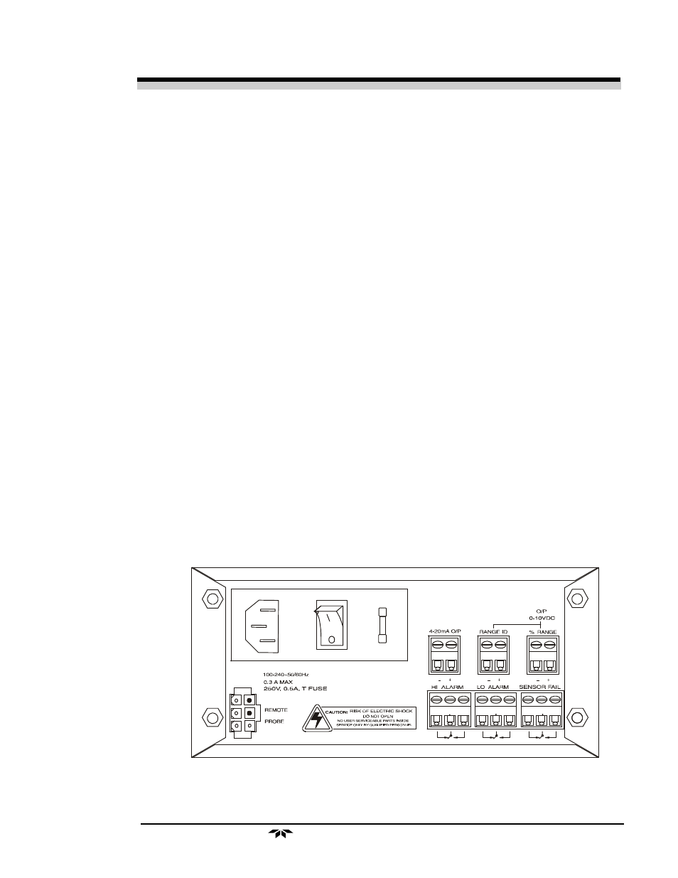
1.4
Rear Panel Description
The rear panel contains the electrical input and output connectors. Sepa-
rate rear panel illustrations are shown in figure 1-2 for the AC and DC battery
backup versions of the instrument. The connectors are described briefly here
and in detail in the Installation chapter of this manual.
Figure 1-2 Rear Panel, Control Unit - AC
(viewed from inside front door)