3 electronics, 5 alarm oxygen monitor operational theory 2, Teledyne analytical instruments – Teledyne 3350 - Microprocessor based control room monitor for personnel safety User Manual
Page 15
2-5
Alarm Oxygen Monitor
Operational Theory 2
Teledyne Analytical Instruments
2.3
Electronics
2.3.1 General
The signal processing uses an Intel
® microcontroller with on-board RAM
and ROM to control all signal processing, input/output, and display functions for
the analyzer. System power is supplied from a universal power supply module
designed to be compatible with most international power sources.
The power supply circuitry is on the Power Supply PCB, which is mounted
vertically, just behind the rear panel of the Control Unit.
The signal processing electronics including the sensor amplifier,
microcontroller, analog to digital, and digital to analog converters are located on
the Main PCB, which is mounted vertically, just behind the front panel of the
Control Unit.
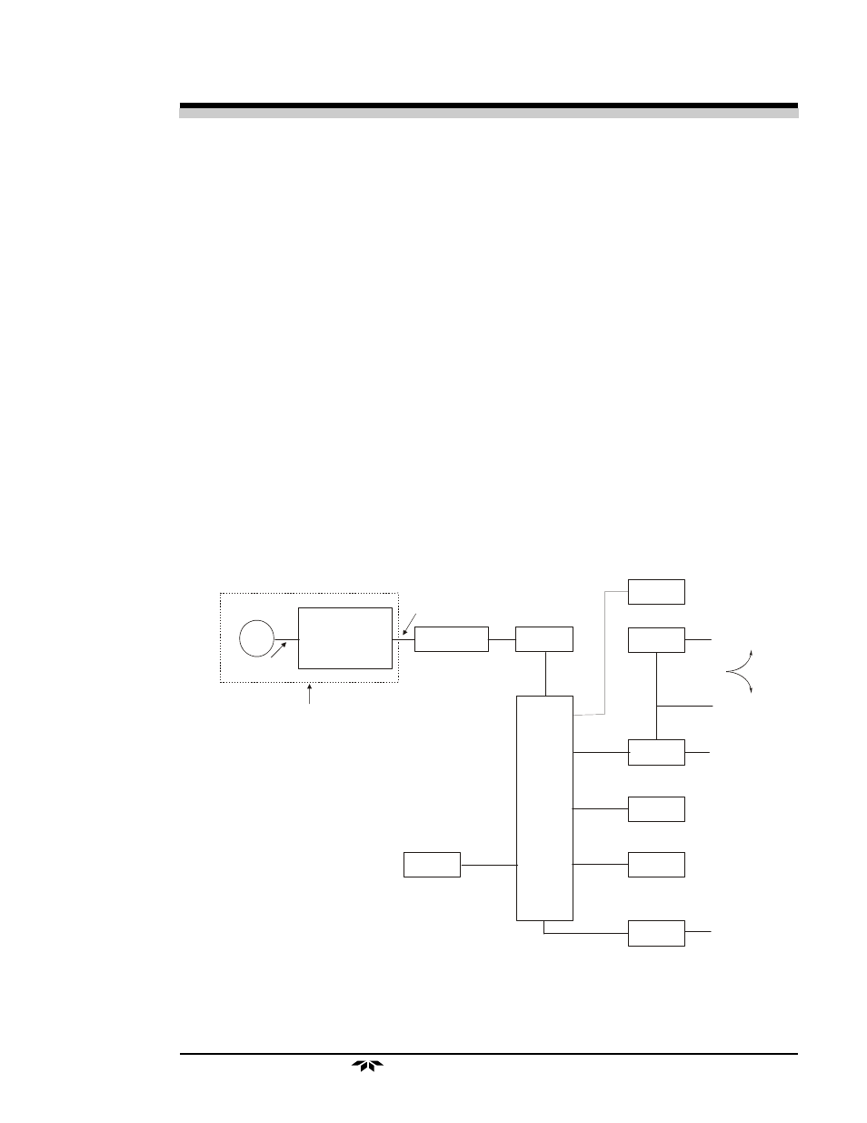
2.3.2 Signal Processing
Figure 2-3 is a block diagram of the signal processing electronics described
below.
Figure 2-3: Block Diagram of the Signal Processing Electronics
ALARMS
DISPLAY
D A C
A D C
KEYBOARD
E–I CONV
SENSOR
AMPLIFIER
TEMPERATURE
COMPENSATION
NETWORK ON
SENSOR PCB
MICRO-
CONTROL-
LER
RELAYS
RS 232
MFC
4–20 mA dc
0–10 V dc
RANGE ID
Concentration
Millivolt
Output
Microamp
Output
Sensor
AUDIBLE
ALARM
(optional)