Teledyne 3000TA-EU - General purpose trace oxygen analyzer User Manual
Page 34
Installation 3000TA-
EU
Teledyne
Analytical
Instruments
22
Fuse Installation: The fuse block, at the right of the power cord
receptacle, accepts US or European size fuses. A jumper replaces the
fuse in whichever fuse receptacle is not used. Fuses are not installed at
the factory. Be sure to install the proper fuse as part of installation. (See
Fuse Replacement in chapter 5, maintenance.)
3.3.2.2
50-P
IN
E
QUIPMENT
I
NTERFACE
C
ONNECTOR
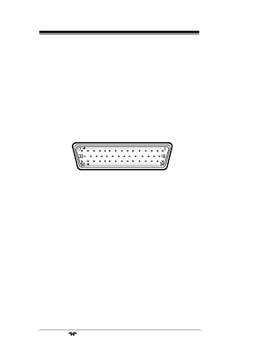
Figure 3-4 shows the pin layout of the Equipment Interface
connector. The arrangement is shown as seen when the viewer faces the
rear panel of the analyzer. The pin numbers for each input/output
function are given where each function is described in the paragraphs
below.
Figure 3-4: Equipment Interface Connector Pin Arrangement
Analog Outputs: There are four DC output signal pins—two pins
per output. For polarity, see Table 3-1. The outputs are:
0–1 VDC % of Range: Voltage rises linearly with increasing
oxygen, from 0 V at 0 ppm to 1 V at full
scale ppm. (Full scale = 100% of
programmable range.)
0–1 VDC Range ID:
0.25 V = Low Range, 0.5 V = Medium
Range, 0.75 V = High Range, 1 V = Air
Cal Range.
4–20 mA DC % Range: Current increases linearly with
increasing oxygen, from 4 mA at 0 ppm
to 20 mA at full scale ppm. (Full scale =
100% of programmable range.)
4–20 mA DC Range ID: 8 mA = Low Range, 12 mA = Medium
Range, 16 mA = High Range, 20 mA =
Air Cal Range.