1 adjusting cell block temperature, 1 adjusting internal temperature 18 – Teledyne 2000XTC - Thermal conductivity analyzer User Manual
Page 28
Installation 2000
XTC
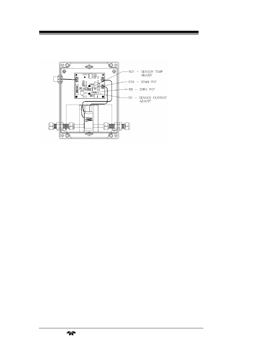
Figure 3-5: Temperature and Calibration Adjustment Location
3.6.1 Adjusting Cell Block Temperature
Note: A separate heater inside the transmitter case controls the
transmitter cell block temperature. It has been adjusted at
the factory for optimum performance based on your
application. Depending on the location of the transmitter
and your process application, it may be necessary to
adjust the temperature of the internal heaters. If
temperature adjustment is necessary proceed with the
following steps, if not, skip this section and proceed with
Zero Calibration. Remove the 4 screws securing the
transmitter cover and lift off the top cover.
To adjust the internal temperature of the transmitter:
1. Allow span gas to flow into the transmitter. Set the flow rate
of the zero gas to between 0.4 and 2 SCFH. As the span gas
is flowing through the instrument, check the output for a
stable reading.
2. If the output is varying over time, increase the temperature of
the internal heater. Using a small flat blade screwdriver, turn
the adjustment screw (R21) clockwise to increase the heater
temperature or counterclockwise to reduce the internal
temperature. The heater set temperature can be measured on
the board at U1 pin 12 (see Table 3.1). Allow 15 minutes for
Teledyne Analytical Instruments
18