Teledyne 2000XTC - Thermal conductivity analyzer User Manual
Page 26
Installation 2000
XTC
4-20 mA Output Signal
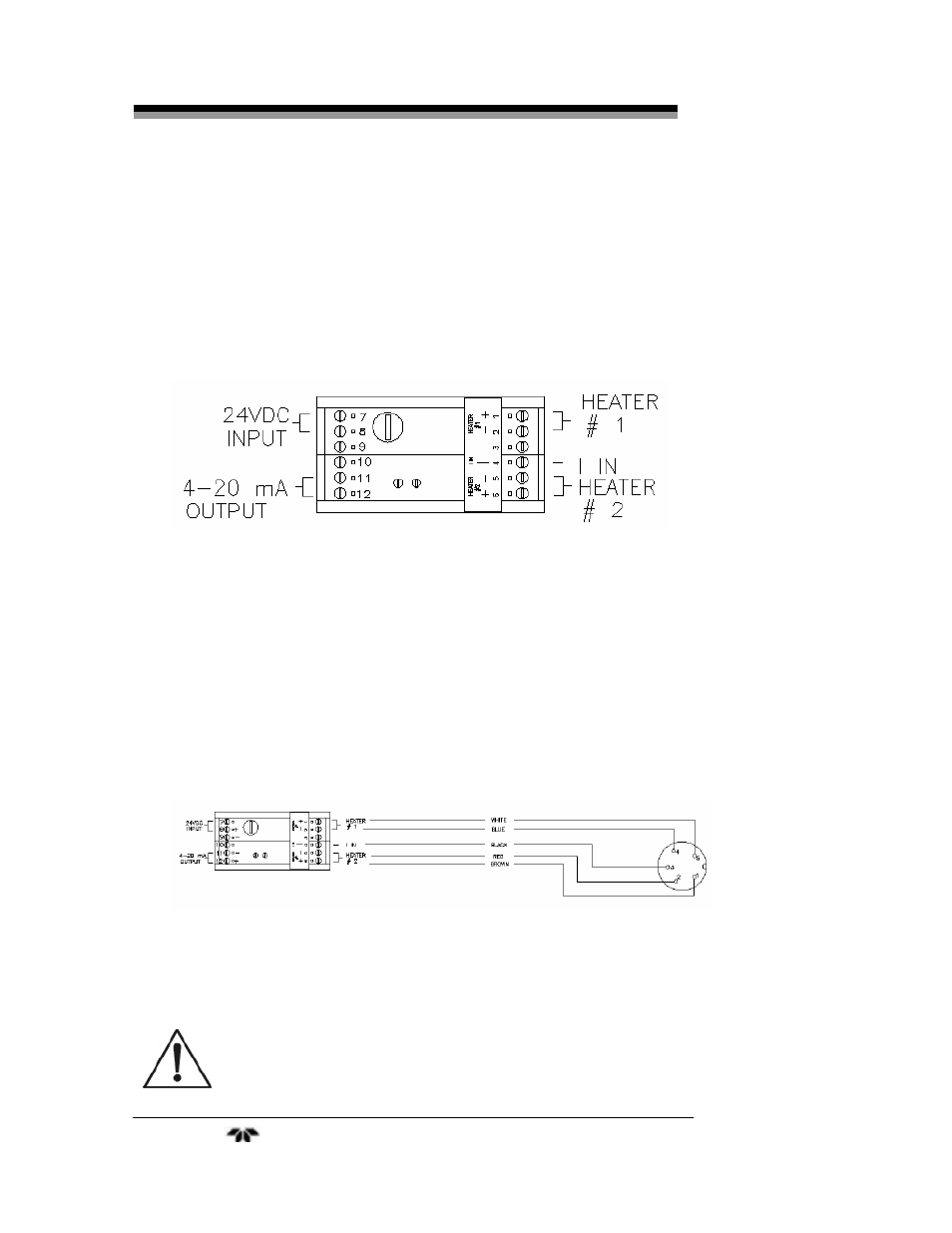
The output signal from the instrument is available to the user as a
4-20 mA current. It has a maximum impedance of 700 Ohms. Typically,
this output is used to display concentration using a digital meter or chart
recorder or to trigger an alarm circuit. Referring again to Figure 3-3,
connect the positive lead to terminal 12 and the negative lead to terminal
11 on the galvanic isolator module.
Figure 3-3: Power and Output Connections to Galvanic Isolator
Module
Interface Cable
The interconnection cable is a 5-wire cable which delivers power to
the heaters and drives the electronics in the transmitter module. It also
passes a 0-4 mA linearized signal back from the sensor circuit to the
galvanic isolator module for output processing. To connect the cable,
insert the 5-pin connector end of the cable to the mating connector on
the transmitter. Connect the other end to the galvanic isolator according
to the diagram in Figure 3-4.
Figure 3-4: Cable Connection to Galvanic Isolator Module
CAUTION:
THIS INSTRUMENT MEETS OR EXCEEDS THE
REQUIREMENTS FOR CENELEC APPROVAL AS AN
INTRINSICALLY SAFE APPARATUS. IN ORDER TO
MAINTAIN COMPLIANCE AND TO ENSURE THE
CONTINUED SAFE OPERATION OF THIS
Teledyne Analytical Instruments
16