5 connection cable, 5 connection cable 11, Figure 2-5: model 2000 xtc external wiring diagram – Teledyne 2000XTC - Thermal conductivity analyzer User Manual
Page 21
Thermal Conductivity Transmitter
Operational Theory
The 24 VDC input is fed to the primary side of an input transformer.
The input circuit is fused via a 400 mA fuse and incorporates a diode
protection circuit in case of accidental reverse polarity connection.
The signal output is also fused, with a 50 mA fuse protecting the 4-
20 mA output terminal. This terminal is also isolated using a high
linearity optocoupler with its own power-limiting circuitry.
Schematic diagrams for both the transmitter and galvanic isolator
are included in the drawing section of the Appendix.
2.5 Connection Cable
The interconnection between the safety barrier and transmitter
modules is accomplished with a 5-wire cable supplied as part of the
instrument. The transmitter end of the cable is fitted with an ATEX
approved 5-wire connector which can only be inserted in one
orientation. The other end of the connector is wired directly to the rear
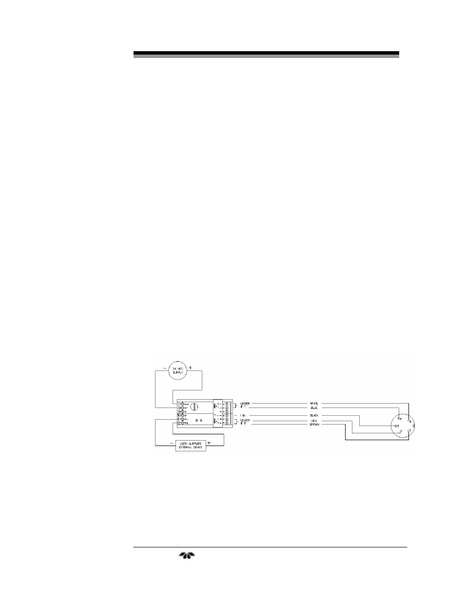
of the galvanic isolator module. The wiring diagram for the galvanic
isolator is shown in Figure 2-5.
The 5-wire interface cable delivers power to the two heaters and the
electronics board. It also carries the 0-4 mA output signal from the
transmitter back to the galvanic isolator unit. Figure 2-5 shows the pin
configuration for this cable. The interface unit and the transmitter
module can be separated up to 30.5 meters (100 feet).
Figure 2-5: Model 2000 XTC External Wiring Diagram
Teledyne
Analytical
Instruments
11