4 electronics and signal processing, 1 transmitter, Figure 2-4: block diagram of 2000 xtc – Teledyne 2000XTC - Thermal conductivity analyzer User Manual
Page 19
Thermal Conductivity Transmitter
Operational Theory
2.4 Electronics and Signal Processing
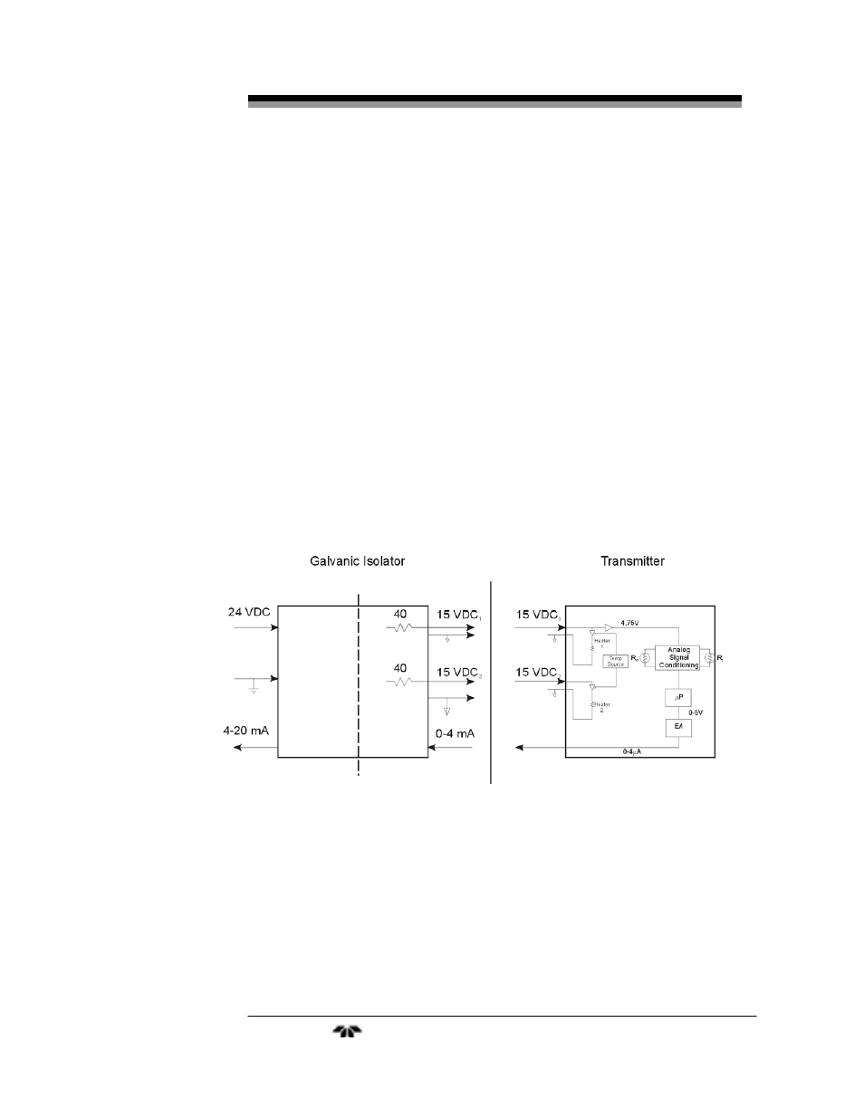
For safety reasons, the electronics and signal processing section are
located remotely from the transmitter module. A galvanic isolator is
employed to limit the current that can be passed through the interconnect
cable to levels that are incapable of providing an ignition source. The
galvanic isolator also provides an optically-isolated 4-20 mA output
signal reconstructed from the 0-4 mA output signal sent from the
transmitter. All electronics in the transmitter are contained on a single
PC board accessible by removing the front cover. The transmitter is
powered from two (2) separate 15VDC lines from the galvanic isolator
module. The galvanic isolator incorporates a 24VDC power supply.
The processing electronics for the sensor are located inside the
transmitter case in addition to the sample cell heaters and E-to-I
converter. The control circuitry for the sample cell heaters, the 24 VDC
power supply, and electronics used to condition the output signal are
located in the galvanic isolator case. Figure 2-4 is a block diagram of the
instrument electronics.
Figure 2-4: Block Diagram of 2000 XTC
2.4.1 Transmitter
The differences in thermal conductivities of the sample gas provide
a small but detectable change in temperature of the resistive sensor
Teledyne
Analytical
Instruments
9