2 mounting the transmitter, 3 mounting the interface unit, 2 mounting the transmitter 13 – Teledyne 2000XTC - Thermal conductivity analyzer User Manual
Page 23: 3 mounting the interface unit 13, Figure 3-1: mounting dimensions for sensor unit
Thermal Conductivity Transmitter
Installation
3.2 Mounting the Transmitter
The Model 2000 XTC Transmitter is intended for indoor use only.
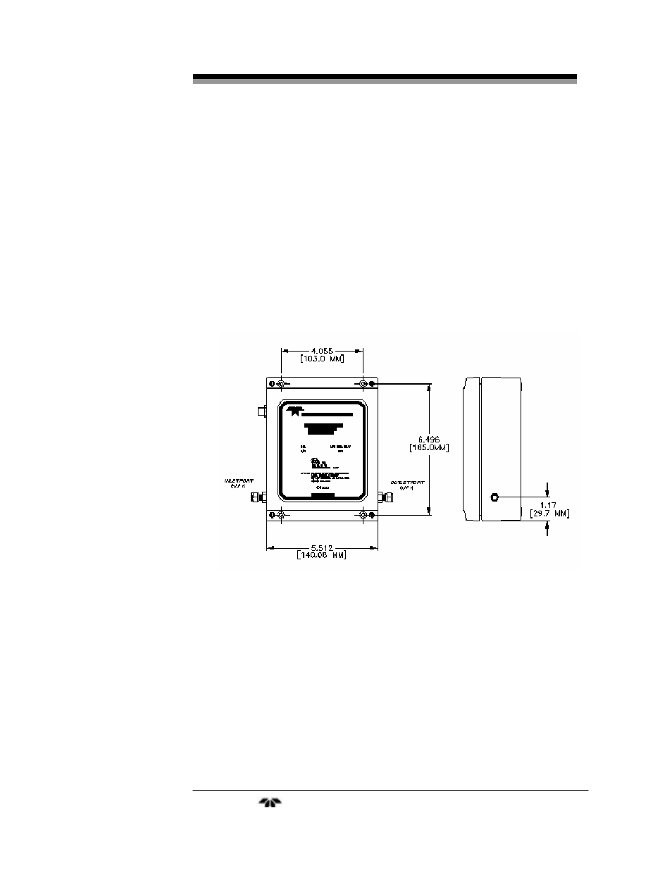
The transmitter module is designed for operation in a hazardous
location. It should be mounted in an area close to the sample take-
off point. Refer to Figure 3-1 for mounting information and
dimensions. The calibration and temperature control adjustment
potentiometers are located under the top cover of the transmitter.
This should be taken into consideration when determining mounting
location. Also make sure there is adequate room to make the sample
system connections. Once a suitable location has been determined,
flush-mount the transmitter using the holes provided in the case.
Figure 3-1: Mounting Dimensions for Sensor Unit
3.3 Mounting the Interface Unit
The galvanic isolator module or interface unit must be located
indoors in a general-purpose location. It can safely be located up to 30.5
meters from the transmitter. This module can either be DIN rail mounted
or panel mounted. The dimensions for this module are shown in Figure
3-2.
Teledyne
Analytical
Instruments
13