Exp. 3: projectile range versus angle, Purpose, Theory – PASCO ME-6831 Ballistic Pendulum_Projectile Launcher User Manual
Page 23: Setup
®
M o d e l N o . M E - 6 8 3 0
E x p . 3 : P r o j e c t i l e R a n g e v e r s u s A n g l e
0 1 2 - 0 5 3 7 5 C
19
Exp. 3: Projectile Range versus Angle
Equipment Needed
Purpose
The purpose of this experiment is to determine how the range of the ball depends on the launch angle. The angle
that gives the greatest range is determined for two cases: for shooting on level ground and for shooting off a table.
Theory
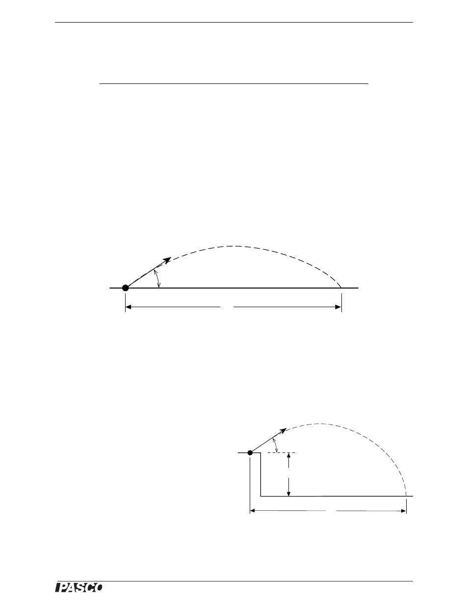
The range is the horizontal distance, x, between the muzzle of the Launcher and the place where the projectile hits,
given by x = (v
0
cos
t, where v
0
is the initial speed of the projectile as it leaves the muzzle,
is the launch angle
above horizontal, and t is the time of flight. See the figure.
For the case in which the projectile hits on a surface that is the same level as the level of the muzzle of the
Launcher, the time of flight of the projectile will be twice the time it takes for the projectile to reach the peak of its
trajectory. At the peak, the vertical speed is zero, so:
where v
0
is the initial speed of the projectile. Solving for the time gives an expression for the total time of flight as:
For the case in which the projectile is launched at an
angle above horizontal from a table onto the floor, the
time of flight is found using the equation for vertical
motion:
where y
0
is the initial height of the projectile in the
Launcher and y is the vertical position of the ball when
it hits the floor.
Setup
1.
Put the Launcher in the top position on the Ballistic Pendulum upright. Clamp the Ballistic Pendulum/Projec-
tile Launcher to a sturdy table or other horizontal surface. Mount the Launcher near one end of the table, but
aim it toward the center of the table rather than away from the table.
Item
Item
Projectile Launcher and plastic ball
Plumb bob and string
Meter stick or measuring tape
Box to make landing area same elevation as muzzle
Graph paper
Carbon paper
White paper
Sticky tape
θ
x
υ
0
Figure 3.1: Shooting on a level surface
v
y
0
v
0
sin
gt
peak
–
=
=
t
2t
peak
2
v
0
sin
g
----------------
=
=
θ
x
υ
0
y
0
Figure 3.2: Shooting from a table
y
y
0
v
0
sin
t 1
2
---gt
2
–
+
=