PASCO ME-8091 Wilberforce Pendulum User Manual
Page 8
®
Model No. ME-8091
Wilberforce Pendulum
7
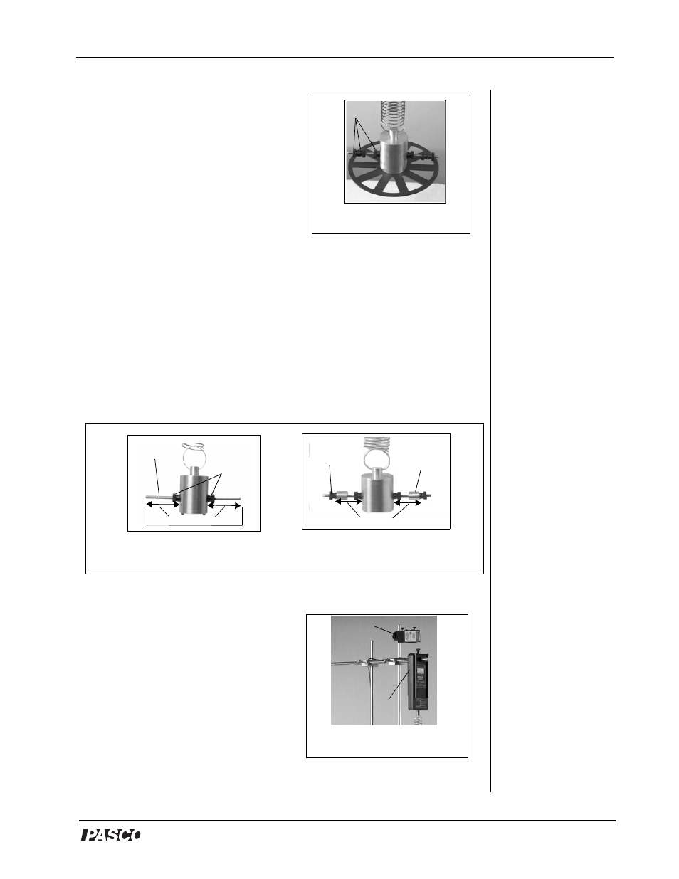
4. a) For setup with Photogate
Wheel: Use a thumbscrew
provided to attach the wheel to the
bottom of the large brass mass.
Screw two plastic masses onto
each side of the brass cylinder bob
(Figure 3). Add another plastic
mass to each side, allowing a gap
between the second mass and the
first mass. Finally, add a third
plastic mass to each side; the third mass is to hold the second mass
in place. (Note: When using the Photogate Wheel, do not put the
brass masses on the crossbar.)
OR
4b) For setup without the Photogate Wheel: Screw a small, plastic
mass over each side on the horizontal cross bar jutting from the large
brass mass. Screw on a brass mass on each side of the crossbar. Use a
measuring tape to ensure each brass mass is equidistant from the bob
in the center. Use two more plastic masses to hold the brass masses in
place (Figures 4a and 4b).
If using an interface, proceed with steps 5-12 that follow.
5. Use the center hole in the Force
Sensor to slide the Force Sensor
over the horizontal rod (Figure 5).
6. Insert the screw from the
cylindrical mount holder into the
bottom hole of the Force Sensor
and rotate to tighten.
Figure 3: Setup with
Photogate Wheel
Plastic Masses
Figure 4a: Crossbar
with plastic masses
plastic
masses
equal distance
brass
mass
plastic
mass
Figure 4b: Brass
masses on crossbar
equal distance
crossbar
Figure 5: Force Sensor and
Laser Mounted on Rods
Laser
Force Sensor
Photogate Wheel