9figure 2.2 • internal wiring diagrams – Detroit Radiant Products Company SV Series User Manual
Page 9
SV
Series
9
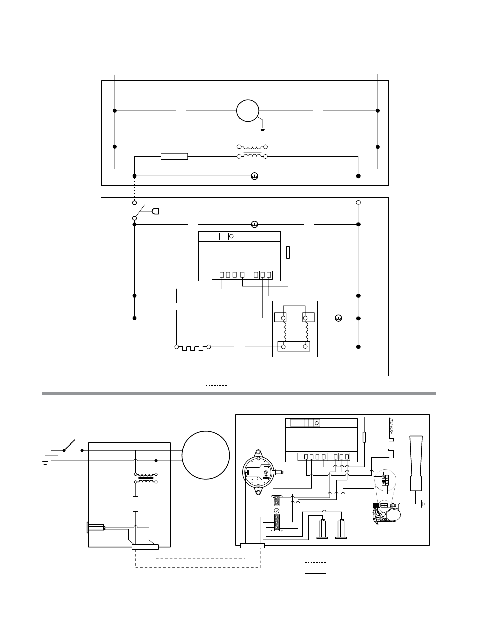
Figure 2.2
•
Internal Wiring Diagrams
A. TP-1251 Ladder Diagram
B. TP-1251 Block Diagram
BK
W
N
L1 120V
Blower
Switch
Light
Valve
Light
Flame
Rod
Gas Valve
Igniter
BK
BK
BK
W
W
G
Y
Y
Fuse
120V
24V
24V Indicator Light
Blower
Motor
120V
24V
Fuse
Indicator
Light
N
L1
120V
Pressure
Switch
Flame
Rod
Igniter
Burner
Gas Valve
Indicator Lights
Terminal
Block
24V
24V
24V
S1 L1 L2 S2
W
M
V
1
GN
D
Field Supplied Wiring
Factory Wiring
LED
ON = Control Fault
2 Flashes = Flame, No Call for Heat
3 Flashes = Ignition Lockout
ON = Control Fault
2 Flashes = Flame, No Call for Heat
3 Flashes = Ignition Lockout
S1 L1 L2 S2
W
M
V
1
GN
D
LED
Ignition Module
Ignition Module
Field Supplied Wiring
Factory Wiring
Burner
Control
Box
Exhauster
Power Box
Assembly
Exhauster Power
Box Assembly
Burner Control Box
2.0
Installation
•
Wiring