0 operation, Warning, Operational indicator lights – Detroit Radiant Products Company SV Series User Manual
Page 13: Sequence of operation
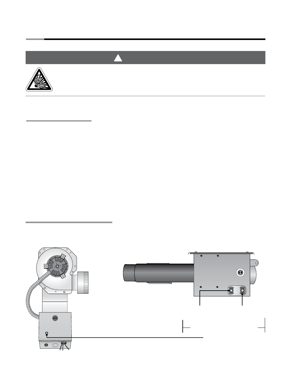
Burner Control Box
Left Panel View
Exhauster End View
SV
Series
13
Figure 3.1
•
Operational Indicator Lights
Light 1
Indicates Power
to Valve
Light 2
Indicates Pressure
Switch Closes
Operational Indicator Lights
VALVE
PS
PRESSURE
SWITCH
V
Power Box Light
Indicates 24VAC
Operational Indicator Lights
WARNING
!
3.0
Operation
NOTE: Reference the Tube Heater General Manual (F/N: LIOGTa) for installation requirements.
Sequence of Operation
Starting Circuit: Upon a call for heat, the exhauster fan energizes creating a negative air pressure
allowing the differential pressure switch to close. A low voltage circuit is completed from the
secondary side of the transformer to the ignition module. After a five (5) second delay, the igniter is
powered. After seven (7) seconds, gas valve opens initiating the ignition trial. If flame is not sensed
after 15 seconds, the heater will attempt to re-ignite for a total of three (3) trials for ignition before
entering lockout mode.
Running Circuit: After ignition, the flame rod monitors burner flame. If sense of flame is lost, the control
closes the gas valve within one second and a new trial sequence (identical to the starting sequence)
is initiated. If flame sense is not established within 15 seconds, the heater will attempt two (2)
additional ignition sequences before entering lockout mode. The control can be reset by briefly
interrupting the power source.
This heater must be installed and serviced by trained gas installation and service
personnel only.
Do not bypass any safety features or the heater’s built in safety mechanisms will
be compromised.
3.0
Operation
•
Sequence of Operation
•
Operational Indicator Lights