Wiring, Thermostat – Detroit Radiant Products Company SV Series User Manual
Page 7
SV
Series
7
Wiring
Figure 2.1
•
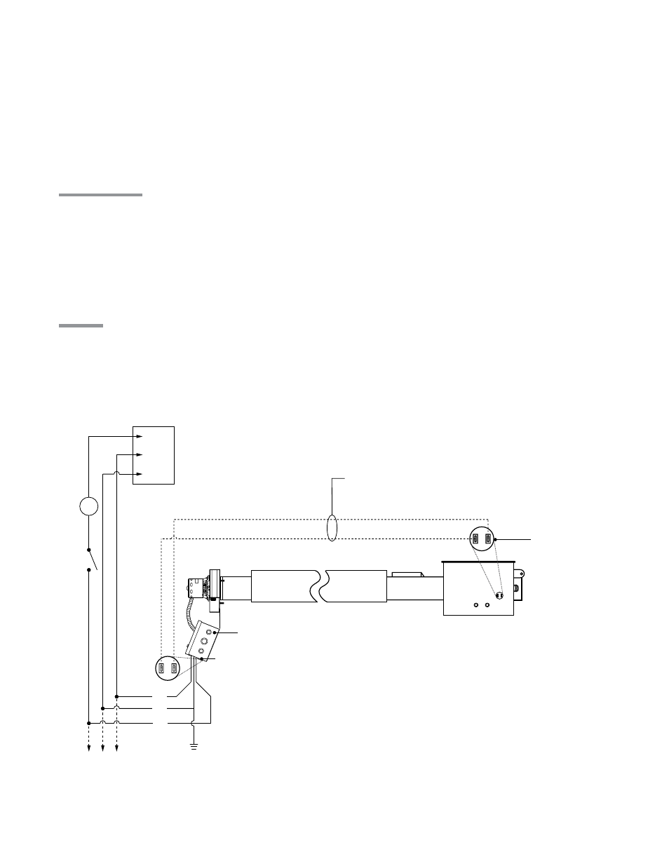
Field Wiring Diagrams
A. Line Voltage Thermostat Wiring - Single thermostat (20 amp), up to six heaters.
L1
Neutral
Ground
T
SV Series
Burner Box
120VAC-60Hz.
Supply
G
BK
W
Low voltage wire (14 ga. multistrand required)
must be installed a minimum of 18 in. from the reflector
and outside of the clearance to combustibles zone.
Up to five
additional
heaters
1/4” female spade
terminals required
(as supplied).
Power Box
1/4” female spade
terminals required
(as supplied).
NOTE: If any of the original wire as supplied with the appliance must be replaced, it must be replaced
with wiring material having a temperature rating of at least 105° C.
Thermostat
SV Series heaters require a 120VAC thermostat to operate.
NOTE: Different thermostats operate
according to their particular features. Refer to thermostat specifications for details.
NOTE: The wire (field supplied) is not where the thermostat is tied into. The thermostat switches the
120VAC supply voltage. Refer to field wiring diagrams (Figures 2.1A & 2.1B).
The use of 14 ga. minimum multi strand wire (field supplied) is required to connect the exhauster
assembly to the burner control box. A round terminal plug accepts two (2) 1/4” insulated female spade
terminals (field supplied).
IMPORTANT: The wire (field supplied) connecting the exhauster power box assembly to the burner
control box
must be mounted a minimum of 18 inches from the top of the reflector and outside of any
other clearance requirements. The span of wire
must allow for several inches of heater expansion.
2.0
Installation
•
Thermostat
•
Wiring